1
\$\begingroup\$

Many low cost LED fixtures have a 2X line frequency flicker. Since flicker free switching LED power supplies are not difficult to design, I assume that flickering drivers are cheaper than flicker free drivers.

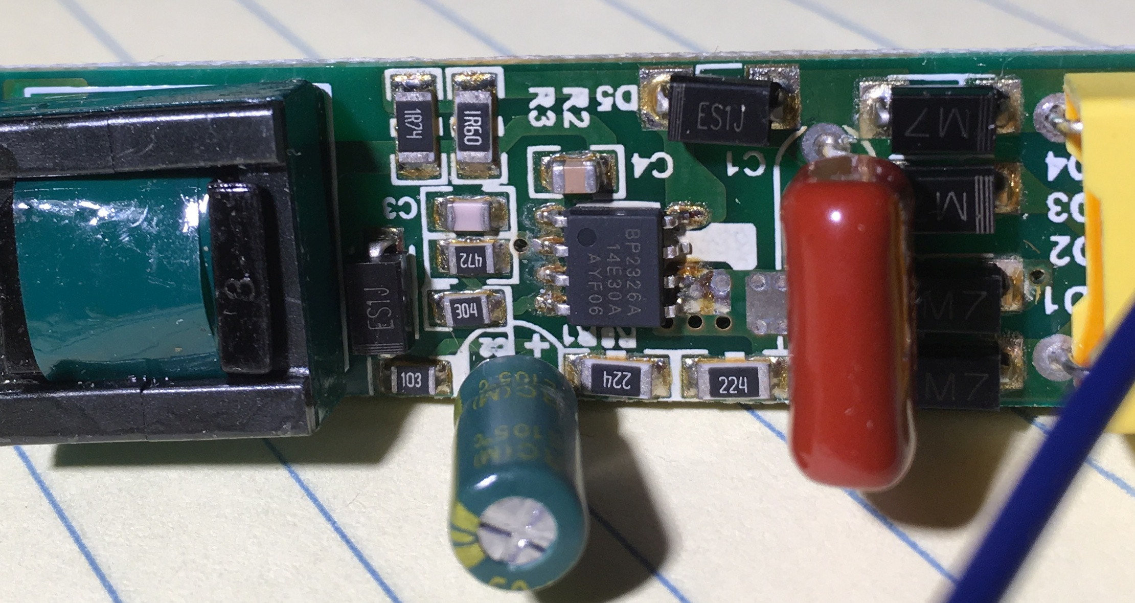
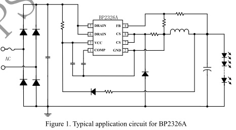
Some pictures of the driver from a low cost 120 Hz flickering LED strip fixture are shown below, followed by the typical application circuit for the on board BP2326A chip from this data sheet.

What is it about flickering driver circuits that makes them presumably lower cost and thus so ubiquitous? LED Drive Board LED Drive Board Back LED Drive Chip LED Drive Circuit

\$\endgroup\$
1
  • 2
    \$\begingroup\$ "Since flicker free switching LED power supplies are not difficult to design" Because flickering LED power supplies are even cheaper to design... \$\endgroup\$
    – Oldfart
    Commented May 1, 2019 at 17:13

2 Answers 2

3
\$\begingroup\$

Basically the input cap across the HV DC bus is hopelessly tiny so the bus voltage pretty much tracks the envelope of the mains.

This means that there is no need for an expensive HV electrolyic and that the power factor is actually quite good even with a simple minded converter like that.

If you want flicker free, you need to hold the bus voltage up sufficiently to avoid the thing dropping out or regulation, and that means a rather large electrolytic. If you also want good power factor, that means an additional PFC stage (at least for simple designs).

\$\endgroup\$
3
  • \$\begingroup\$ Thanks for spotting the labeling error. I updated the pic. \$\endgroup\$
    – crj11
    Commented May 1, 2019 at 17:28
  • \$\begingroup\$ Because an LED is current driven wouldn't it be more accurate to say " hold the current up sufficiently". And this would require a sufficient inductor (not capacitor) to keep the output in Constant Conduction Mode (i.e flicker free)? Notice the expensive component (inductor) is on the LED output side. I doubt the output electrolytic is of much value. \$\endgroup\$ Commented May 8, 2019 at 3:31
  • \$\begingroup\$ @Misunderstood Agree that the output elco does half of nothing, but no reasonable switchmode inductor is going to do really help much when the input bus drops way below the output voltage they are just too small to hold enough flux. The solution is to hold the input side bus voltage up so that the thing can run in normal buck mode (of whatever variety) and it is this cap that adds the cost. Flicker free is IMHO far more about 100/120Hz flicker then switchmode frequency flicker which is mostly irrelevant outside of filming. \$\endgroup\$
    – Dan Mills
    Commented May 8, 2019 at 10:24
2
\$\begingroup\$

Cheaper? How much?

Magnetics are usually the biggest cost driver.

In budget SMPS designs in the 14 watt range such as this one, the cost differential is in the most expensive parts for low ripple current.

a) the magnetics must be ferrite which has higher cost vs laminated steel for high switch freq. vs 50 Hz LPF with 100 Hz flicker during dropouts.

  • The ferrite must also support higher surge currents to store more energy and up to 10x the low DC current at the maximum DC voltage.
  • This could mean an external 5A FET for low cost or 9A for high efficiency.

b) add external FET necessary to store energy with low loss.

  • The IC cost is fairly low on the sorted $BOM scale.

c) The input cap is the 3rd cost driver about $0.60 on Ebay or

\$\endgroup\$

Your Answer

By clicking “Post Your Answer”, you agree to our terms of service and acknowledge you have read our privacy policy.

Not the answer you're looking for? Browse other questions tagged or ask your own question.