1
\$\begingroup\$

Skutt Kiln

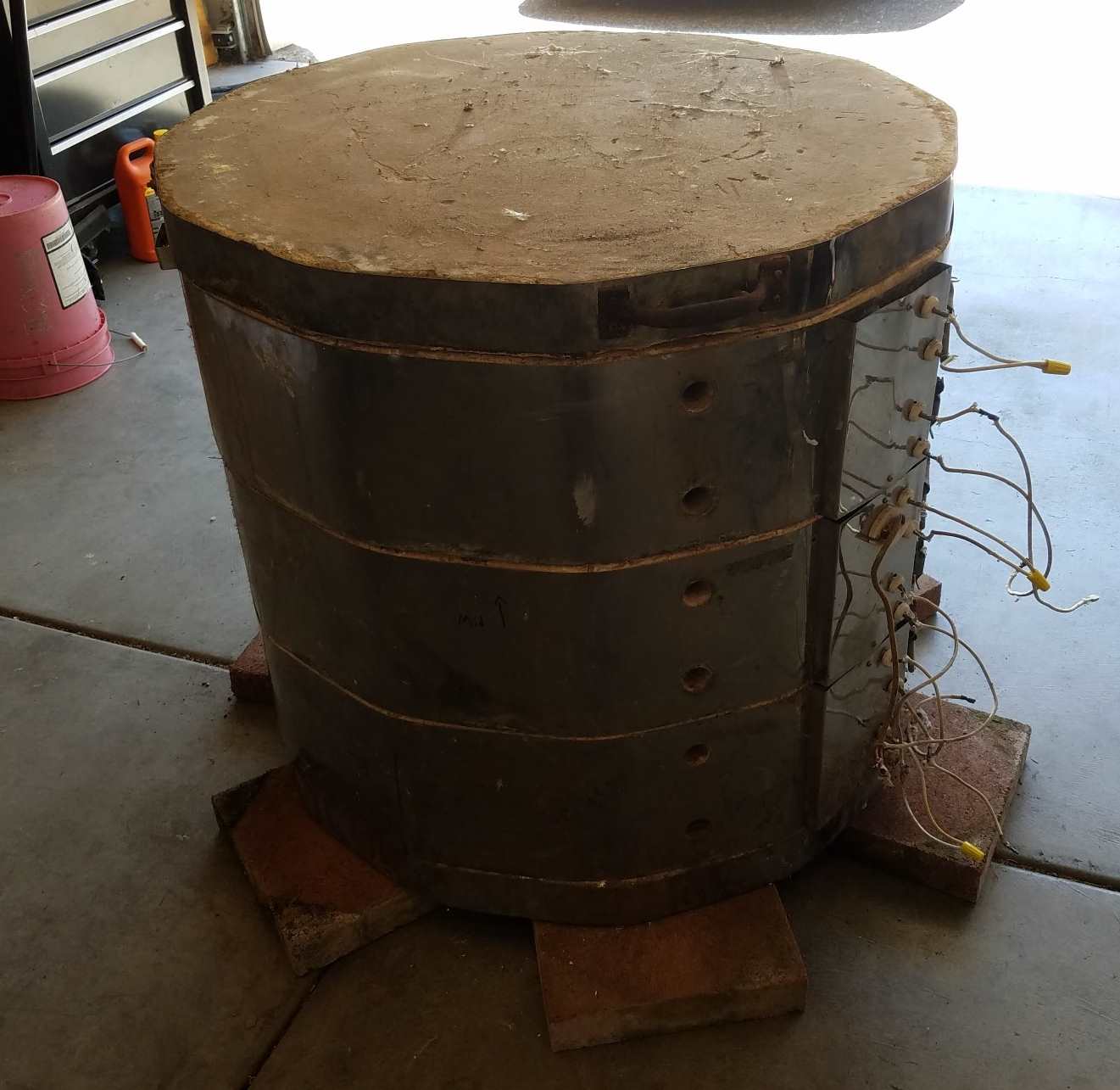
I was given a Ceramics Kiln that is designed for 208V and I am trying to see if there is a way I can run it at 240V. It has 6 elements made of 16AWG Kanthal APM resistance heating wire. Each element having a resistance of 26 ohms. Elements are wired in parallel pairs.

I tried changing the element pairs to run in series to reduce the voltage across each element to 120V. This worked; but, the power reduction was too much and the kiln only got to 1100F. Goal is at last Cone O4 (1945F) with stretch goal to Cone 6 (2232F).

My next thought is to try running the some of the elements at 240V. This would be 9.2A compared to the 8A at 208V; but, I would really like to know if the wire can safely handle the 9.2A before I risk damaging the element wires.

How to figure the max current capacity for different gauges of Kanthal wire. I have been looking for a while and I can't find anything.

Update: I ran a test with some of the elements at 240V and they did not fail; but, presently I am testing using a 30A circuit so I can't run more than 3 elements. I have to move the kiln to a different location to test with 50A (which would allow me to run up to 5 elements. This empirical test is nice; but, I would like to have some analysis to know how much margin I have.

\$\endgroup\$
1
  • \$\begingroup\$ if the wire can hadle 33% more power mainly depends on how close to the limit it is in its original setup... the wire's proably fine for 10A with forced air cooling, but in a confined space the limit will be lower \$\endgroup\$ Commented Jul 28, 2019 at 3:00

2 Answers 2

2
\$\begingroup\$

well, at 240V not that extra 15% voltage (over 208V) makes 33% extra heat. That could well be too much heat.

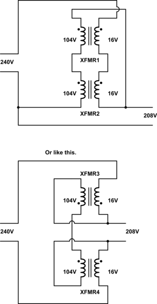
If you can get two microwave oven transformers and replace the secondary windings with 16V windings (about 16 turns of wire) you can build a step-down autotransformer,

schematic

simulate this circuit – Schematic created using CircuitLab

such a setup should be good for 60A output with no problems.

Running the primariries at 104 instead of 120 will significantly reduce heating of the transformer as they are normally run fairly close ot saturation.

\$\endgroup\$
8
  • \$\begingroup\$ 220V was a typo, I'll correct it above. The 9.2A was based on 240V / 26 ohms \$\endgroup\$ Commented Jul 28, 2019 at 2:55
  • \$\begingroup\$ ok, it's still 33% more power at 240V \$\endgroup\$ Commented Jul 28, 2019 at 2:57
  • \$\begingroup\$ Interesting approach for converting 240V to 208V. It would reduce the current further and allow me to run lower current on the 240V line. \$\endgroup\$ Commented Jul 28, 2019 at 3:03
  • \$\begingroup\$ When "makers" and high currents are involved, the M.O.T. is a go-to piece of hardware. \$\endgroup\$ Commented Jul 28, 2019 at 3:06
  • \$\begingroup\$ It is only 33% more power if I run all the elements. My plan is to only run 5 of the 6 elements (not run the top one). \$\endgroup\$ Commented Jul 28, 2019 at 3:07
2
\$\begingroup\$

The power required to raise an insulated oven to a certain temperature depends on the insulation resistance of the oven and the thermal conductance of the heater to the inner air.

Without these design parameters, one can only guess where your problem lies.

Since Pd=V^2/R and R has a PTC effect at least (est.) 1:5 for red hot and in white lightbulbs 1:10 to 2800'K

The cold resistance is thus increased with temperature of the wire.

Since /$Pd=V^2/R(T)/$ and R(T) rises with T the cold power for 240V is Pd(26 Ohms)=2.2kW and for 120V is Pd(26 Ohms)=553W when this temp rises as I expected R(T) rises 1:5 thus reducing power to 20% initial power.

My suggestion is use a Triac dimmer with 240Vac to raise the power slowly so that it does not fuse and burnout out when cold (240V/26 Ohms)= 9.2A and increase voltage phase as it heats or design it properly so that the current starts lower and then becomes more constant as you increase the voltage with temperature. (design beyond scope of this question without more details, but basically lies in the thermal conductance of wire to air inside the oven)

\$\endgroup\$
3
  • \$\begingroup\$ Yeah a 50A triac dimmer (or smaller dimmers per element) is another option. you might experience "some": RF interferance. triac heat dissipation is about 2W per A so 100W total which ever way you go. Resistance wire has a vert low thermal coefficient of resistance, so don't count on the resistance going up by much from cold to orange-hot. For Kanthal from 0 to 1400C the resistance only increases by 5% \$\endgroup\$ Commented Jul 29, 2019 at 3:48
  • \$\begingroup\$ @Jasen to reach air temp of 1513'K (2232'F) I might expect 2000'K wire temp for heater to reach that in a reasonable time. but I have not measured these which is what I assumed for the cold start current and thus a larger PTC effect. \$\endgroup\$
    – D.A.S.
    Commented Jul 29, 2019 at 5:22
  • 1
    \$\begingroup\$ above 1800K you'll see a rapid increase in resistance as the wire melts. \$\endgroup\$ Commented Jul 29, 2019 at 6:29

Your Answer

By clicking “Post Your Answer”, you agree to our terms of service and acknowledge you have read our privacy policy.

Not the answer you're looking for? Browse other questions tagged or ask your own question.