1
\$\begingroup\$

When reading through the datasheet of the ADS1298 (an analog Front-End for Biopotential Measurements) I noticed the schematic on page 42 (see below):
It is possible to select or deselect the positive and negative input of each channel with corresponding configuration bits (RLDxP and RLDxN).

I have two questions regarding this flexibilty:

  1. RLD is used to reduce the CM noise with negative feedback of the CM signal to the patient. This typically requires me to sum both the negative and the positive input, otherwise I would not only feed back the CM part, but also parts of my signal.
    So why would it be useful to select only the negative or only the positive input of a signal? TI offering an additional register to make this possible suggests to me that there probably is a use case for this.

  2. I guess it does not make sense to switch different inputs to the RLD amp between my measurements (reading all 8 channels at 2kSPS), because this feedback loop has some settling time and I want to keep this loop running stable. So I assume the typical application will be to set the RLD config once and than keep it running like that for the most time (unless something happens, like the detection of a loose electrode). This means I won't use Ch1 inputs for the RLD when measuring Ch1 and Ch2 inputs when measuring Ch2 and so on.
    Do I typically simply use all my input channels by closing all switches or would I choose one input channel and only use that for all the measurements?
    In case this is depending on the application: I want to build a wristband with 8 EMG electrodes, but I would assume this to be similar for ECG or EEG.

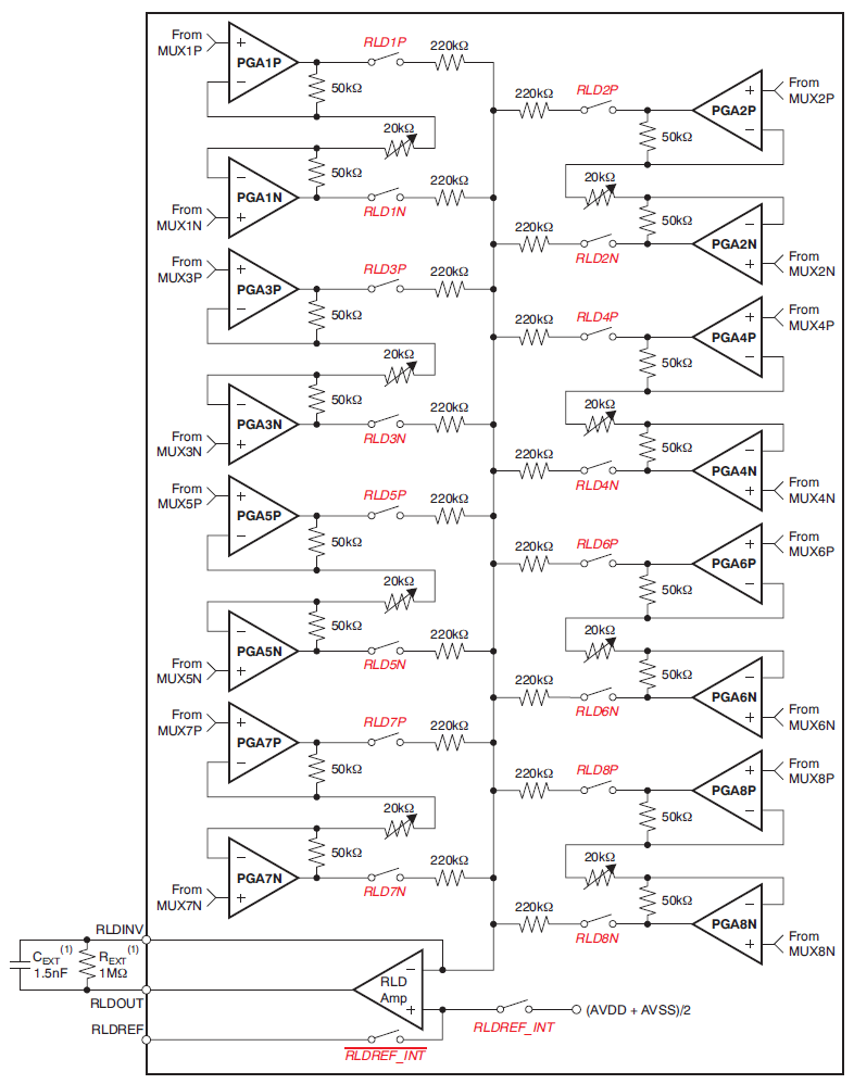
enter image description here

\$\endgroup\$
1
  • \$\begingroup\$ I designed and tested various EEG/ECG/EMG amplifiers for my BioMed class and show 'N tell in '74 and knowing that the only difference is the signal level and optimum BW to match the signal spectrum. They were noisefree with good electrodes and CMR principles for balanced inputs. Also having been to emergency several times recently, it seems they only use 12 point ECG with thumb sized sticky tapes and edges that can easily grabbed with small alligator clips. They were all std. colour-codes and the result was an instant computer analysis But the Triage Nurse just ignored it. Too bad. Use all 11 \$\endgroup\$
    – D.A.S.
    Commented Jan 21, 2020 at 21:39

2 Answers 2

3
+100
\$\begingroup\$

Good questions! In addition to the common-mode noise reduction, the amplitude of the common mode voltage must remain small in order for the programmable gain amplifiers to operate at high gains without saturating the input stage. Using a single input from one of the differential input pairs is less ideal, but is still effective because of the low-pass filter being applied to the right-leg drive signal and the fact that the inputs are still differential. Certainly, closing all of the switches in use gives the best result assuming that you have good connections everywhere.

The purpose of the feature is to provide the ability to de-select individual inputs in the event that there is a loose connection. Because of the high impedance of the amplifier inputs, an open connection on an input channel, if used to determine the RLD signal, would float and likely interject enough noise and offset to drive all of the differential channels out of their operating range. The device can detect a loose electrode, allowing you to eliminate its contribution to the RLD drive signal, thus maintaining common mode rejection and preserving the performance of the remaining electrodes. Choosing a single electrode or electrode pair makes the performance completely dependent on the connection quality of the specific electrode(s) you have chosen. As an alternate approach to address intermittent or bad connections, you could use this feature to allow the operator to switch between electrode pairs for RLD generation, selecting one which gives the desired result. The operator could then easily find the loose or intermittent electrode.

Good luck!

\$\endgroup\$
2
  • \$\begingroup\$ And using more than one electrode pair won't decrease the driving voltage? Because all used input channels are summed before going to the RLD amp: If I use one elctrode as input, the amp tries to drive the negative input to the middle of the power supply. But when I sum two inputs together I have a higher current in the node of the negative input and this will change the driving output to a more negative voltage, or am I wrong here? That's why I figured I might have to use only one input, when I want the RLD driving voltage at Vcc/2. \$\endgroup\$
    – jusaca
    Commented Jan 21, 2020 at 10:32
  • \$\begingroup\$ The circuit is more designed to provide the effect of averaging the baseline of the inputs, since the goal is to minimize the "DC" component from any of the inputs with respect to Vcc/2. You can choose Cext and Rext to adjust the overall gain and the low-pass filtering of the RLD if necessary. However, there is nothing wrong with your approach either, as long as you have a good connection, and you can always provide the ability for the operator to switch between sources for RLD. Remember, the RLD output is inside a feedback loop itself since each PGAxN output will change as the RLD moves. \$\endgroup\$ Commented Jan 21, 2020 at 14:29
1
\$\begingroup\$

With respect to (1), I can't offer much input except to say that perhaps there's an odd use case where somebody uses the system in a single-ended configuration where this makes sense. Another possibility is that this functionality might be important for lead-off detection, or the plethysmogragphy mode for respiration detection. It's a fairly beefy chip, with a variety of bells and whistles, and one of the bells and whistles you're not using might explain the need for this functionality.

For (2) my intuition is that you should just select one channel and stick with it. The nature of the common-mode noise is that it will be fairly uniform across the body, as the noise you're interested in is largely a manifestation of the impedance of the body connection to the reference electrode. Once the noise is on the body, the 300mOsm fluid all over the body is a pretty good conduction system.

I think there's also an argument to be made in terms of failure modes. If each 'trode has a certain percentage chance of having a failed attachment, your chances of corrupting the CM signal with a failed electrode is the sum of the the probabilities across channels.

Lastly, the good thing about choices like this is that changing a value to one or two registers can undo the choice in moments!

\$\endgroup\$
3
  • \$\begingroup\$ This makes sense, I guess. But I'm not sure what you mean with your last sentance? \$\endgroup\$
    – jusaca
    Commented Jan 16, 2020 at 9:13
  • \$\begingroup\$ If you don't get the performance you expect, changing it is a code issue, not a hardware change, so move forward with the confidence of knowing that fixing a poor choice here doesn't get much easier. \$\endgroup\$ Commented Jan 16, 2020 at 11:33
  • \$\begingroup\$ That's true! I will do my own testing as soon as I have the testboard, but I wanted to check what the common practice is first. \$\endgroup\$
    – jusaca
    Commented Jan 16, 2020 at 12:20

Your Answer

By clicking “Post Your Answer”, you agree to our terms of service and acknowledge you have read our privacy policy.

Not the answer you're looking for? Browse other questions tagged or ask your own question.