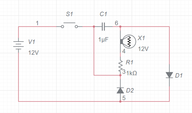
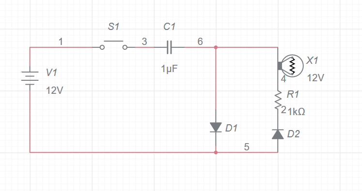
Update Please evaluate this third attempt:
 This is my first electrical project, so please be gentle with me. I know very little about electronics.
I'm building a machine that has a crank that users pull. The ideal behavior is that when a user releases the crank from its lowered position, the circuit will drive the load (represented by the lamp) for a few seconds, then turn off. Translated: When S1 is first opened, C1 drives X1 for a few seconds, then X1 shuts off. When S1 is closed momentarily, the cycle repeats. To be clear, X1 isn't driver while S1 is closed. I expect that there are better solutions with a different type of switch than S1 (instantaneous button), but in the greater mechanical context, it seems like the only practical choice for the project.
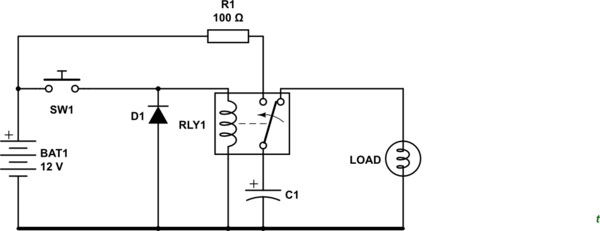
Here's a diagram of my first attempt at the circuit. Please ignore the actual quantitative values, I just want to get the circuit working conceptually. Please let me know if I got the diode directions right. Also, the load is actually a relay, I just wasn't able to find the symbol for that.
My conception is that when S1 is closed, C1 charges via D1. When S1 opens, C1 discharges via X1. I think the main weakness is that C1 is connected in parallel with the short circuit to V1. What do you think?


