1
\$\begingroup\$

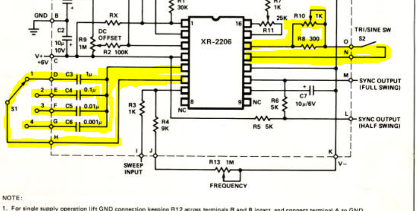
I want to switch on/off the shown parts of a circuit using a transistor, which will controlled by an Arduino, please see the picture below - the yellow marked ones. The circuit is build around a XR2206, which is a function generator IC.

The left side controls the range the function generator is working in, by adding different capacitors between pins 5 and 6 of the XR2206.

The right side just switches between triangle or sine wave generation, by adding some resistance between pins 13 and 14 of the IC.

schematic diagram

Now, I can easily switch circuits which are connected to ground using NPN, but I fail to come up with a solution for this problem.

I am ready to accept any laughter. If I am using wrong terms etc, please give me a pointer to the right one. In the old times I would have used relays to achieve this, but I get this is too much old style and overkill for this issue here.

\$\endgroup\$
9
  • \$\begingroup\$ I didn’t think the XR2206 was still around. But I looked up the Sparkfun 2006 EXAR datasheet and pin 12 is GND \$\endgroup\$
    – D.A.S.
    Commented Feb 21, 2020 at 13:04
  • \$\begingroup\$ Can you be more specific with your question - you say you can easily do it with NPNs so is it only the right hand connection you need solving? \$\endgroup\$
    – Andy aka
    Commented Feb 21, 2020 at 13:09
  • 2
    \$\begingroup\$ A quad analog switch seems to solve this. \$\endgroup\$
    – D.A.S.
    Commented Feb 21, 2020 at 13:10
  • \$\begingroup\$ The XR2206 has been around for a long time and, to be honest, my experiences with it are not so great. If you tell us what you exactly want to build there may be newer and better alternative which have been developed in the last 20 years. \$\endgroup\$
    – Oldfart
    Commented Feb 21, 2020 at 13:21
  • \$\begingroup\$ @Andyaka: solving the connection Pins 13/14 would be a good start, yes \$\endgroup\$
    – P.S.
    Commented Feb 21, 2020 at 16:50

2 Answers 2

2
\$\begingroup\$

When using a transistor as a switch, the "switching action" depends on the voltage between the base and emitter (or gate and source for a FET). But in your circuit the emitter voltage is a varying analog signal. This makes producing the correct base drive difficult.

Enter the analog multiplexer, an IC designed specifically to switch a varying analog signal with a DC control signal. There are many to choose from, but the lower cost parts probably will not work well in your circuit. All analog switches have an input-to-output resistance when "on", which will affect the frequency (for the capacitor switch) or waveform shape (for the tri/sine switch). Do some reading on analog switches and multiplexers and see if they will work for you.

\$\endgroup\$
1
  • \$\begingroup\$ Thanks for pointing this out. Seems these analogue switch ICs could solve my problem. I will give it a try. \$\endgroup\$
    – P.S.
    Commented Feb 21, 2020 at 16:51
1
\$\begingroup\$

Just to provide the solution I found. Both marked parts of the circuit I was not able to solve by single transistors or analog switches. But opto couplers did the trick.

Thanks to all people who joined this. Appreciate your input.

PS: not saying the analog switch thing is wrong - however, I was not able to solve with the ICs I had on hand.

\$\endgroup\$
1
  • \$\begingroup\$ Optocouplers can be a good choice, especially if you use 'PhotoMOS' types which are bidirectional. Analog switches should work too, but only if the bias/control voltage is sufficient to operate them properly throughout the analog voltage range. \$\endgroup\$ Commented Mar 1, 2020 at 0:53

Your Answer

By clicking “Post Your Answer”, you agree to our terms of service and acknowledge you have read our privacy policy.

Not the answer you're looking for? Browse other questions tagged or ask your own question.