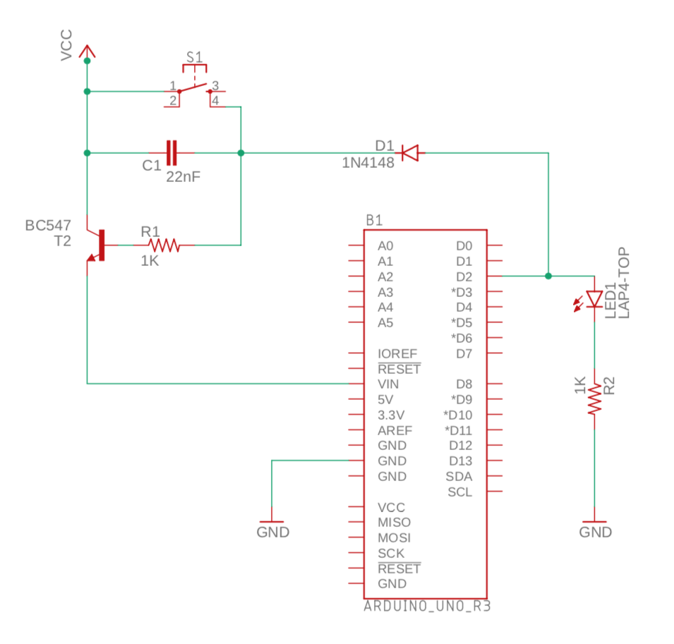
I have built the circuit as shown below. The goal is to power the Arduino by battery and maximise battery life by turning off power when it is not in use. There is no need for the Arduino to wake up periodically or anything like that. The only "wakeup" will be when the switch is closed.
The idea is that an external action (pressing S1) will power up the Arduino. The Arduino will do whatever it needs to do (e.g. report the action) and then power off.
The powering up of the Arduino on press of S1 works just fine.
The first thing that the Arduino will do is to raise D2 high. This also seems to work fine as the LED1 lights up.
However, when I release S1, power is immediately cutoff.
My expectation is that since D2 is high, this will keep the transistor (T2) turned on until such time as the Arduino "does whatever it needs to do" before taking D2 low.
For the purposes of testing, I rapidly blink the inbuilt LED for 3 seconds before taking D2 low. this achieves three things:
- I know that the Arduino has "booted up" and that D2 is HIGH (I can also see this on LED1)
- The rapid blinking shows me that the Arduino is powered up (which is useful to observe the failure case of D2 going low but for some reason this fails to cause the Arduino to power off).
- Gives me time to hold hold S2 closed long enough for the Arduino to "boot up" and allow me sufficient time to release S2 before the 3 second operation (rapid blinking of the builtin LED) completed.
However, as mentioned above the instant I release the switch S2, the Arduino's power is immediately cutoff.
I have tried removing the LED1 - to "force" all power from D2 through the transistor, but this does not seem to change anything.
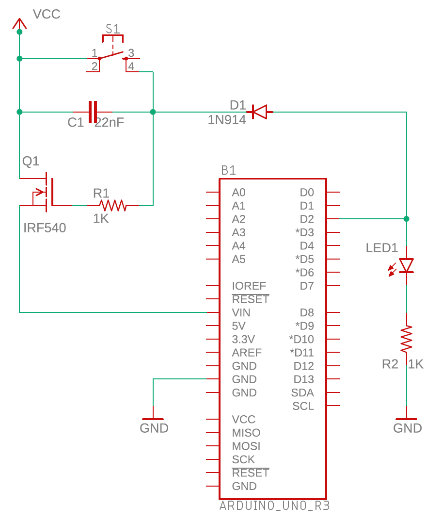
Following is the circuit diagram. The purpose of the diode (D1) is to protect the Arduino's digital pins from the 9V, but allow the Arduino's D2 signal out to control the transistor. The capacitor C1 is intended to provide a bit of debounce for the switch.
After the circuit diagram is the test program.
Obviously I have no idea why this doesn't work. So my question is why does this not allow the Arduino to take control of it's power supply via the transistor and it's digital output on Pin 2 (with or without LED1)?
Here is the test program. The comments should clarify the intention of the main parts of the program:
#define POWER_CONTROL_PIN   2

void setup() {
  // put your setup code here, to run once:

  pinMode(LED_BUILTIN, OUTPUT);
  pinMode(POWER_CONTROL_PIN, OUTPUT);
  digitalWrite(POWER_CONTROL_PIN, HIGH);      // Turn on the transistor to maintain the power flow.

  Serial.begin(9600);
  while (!Serial) {
    delay(10);
  }
  Serial.println("Arduino Controlled power switch - Ready");
}

// Rapidly blink the inbuilt LED to show that the Arduino is "alive"
void blinkLED(int duration) {
  digitalWrite(LED_BUILTIN, HIGH);
  delay (duration);
  digitalWrite(LED_BUILTIN, LOW);
  delay (duration);
}

void loop() {

  Serial.println("Operations mode - rapid blink");
  for (int i = 0; i < 10; i++) {
    blinkLED(150);
  }

  Serial.println("Shutting down mode");
  digitalWrite(LED_BUILTIN, HIGH);            // Signal that we are about to shutdown by holding the inbuilt LED on for two seconds.
  delay (2000);
  digitalWrite(POWER_CONTROL_PIN, LOW);       // Turn off the transistor to terminate power flow.

  digitalWrite(LED_BUILTIN, LOW);             // We should never get here ('cos the power has been turned off), but just in case,
  delay (250);                                // repeat the rapid led blinking to show that we are still "alive".
}


