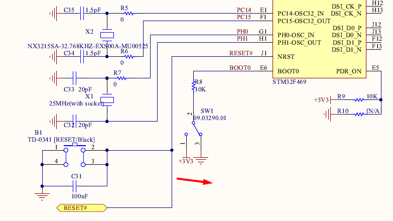
I am designing a custom PCB based on STM32F401RCT6 microcontroller. I am using SWD interface and STlink to program and Debug the micro controller.
I understood that reset pin is used to RESET the MCU which includes all the registers clocks etc. When Reset pin is connected to ground externally it is in Reset state when it is not connected to ground it is not in reset state.
I also understood that the ST-LINK resets and then sends the program through SWD interface.
Question 1:
My question is how ST-Link resets because as per datasheet Reset pin of the micro controller should be connected to the ground via button switch so that we can manually reset by pressing it. But when I refer to the schematics to connect the reset pin to SWD interface, I saw two connections: one is via button switch to ground and another is directly connected to the SWD connector. Then I got confused like the reset pin is connected to ground via button switch and how STlink will reset the MCU when Reset pin is directly connected to the SWD connector without connecting it to ground.
So when we want to reset we need to do manually reset by pressing button. If it is like that then why we need reset pin for SWD interface to ST link?
Or is it like Inside Stlink Programmer Reset pin is connected to GND. So for automatic reset via STlink we are using RESET pin in SWD interface and for manual reset we are using button. Am I correct? If I am wrong correct me.
And my other question is: I am using SWD interface for programming and debugging since I am using SWD interface and not using Bootloader, should I connect Boot0 pin to ground. Or is there any use of Boot0 pin (Bootloader) while programming using SWD interface?

