0
\$\begingroup\$

I have an IC (KIA7025AP) on my power PCB. I need to check if it's faulty.

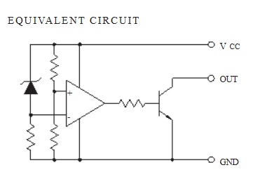
Function of this IC is accurately resetting the system after detecting voltage at the time of switching power on and instantaneous power off in various CPU systems and other logic systems.

Could you please explain this to me, knowing it's used in the power PCB of a washer.

What is are appropriate tests to apply to this IC using a DMM?

I don't have oscilloscope.

enter image description here

Needless to say that I don't want to remove it from the circuit unless it's necessary.

Although exposure to high temperature is inevitable during soldering, we recommend limiting the soldering temperature to low levels for the sake of retaining inherent excellent reliability.

I know you going to ask me why do you doubt this IC.

  1. Many users came across the same problem I have, replacing the power PCB solved the problem of the washer not to start, though it powers up and you can change the washing programs etc.

  2. I tested most components (triacs, relay, electrolytic capacitors, varistors, etc) and they're good.

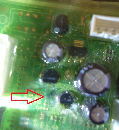
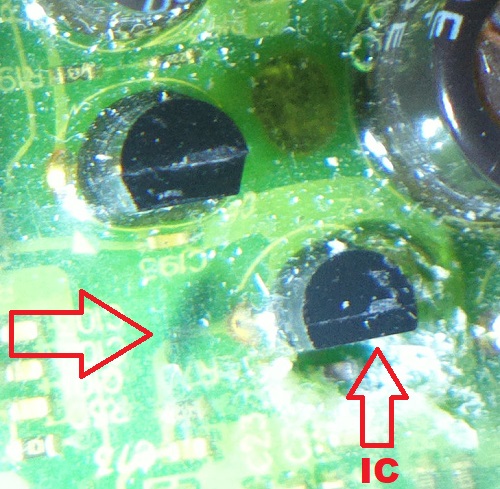
  3. Visual inspection showed a black material right next to its left terminal (VCC) under the wax, it could be an indication of a faulty IC or could be nothing at all.

enter image description here

enter image description here

\$\endgroup\$
5
  • \$\begingroup\$ Again, in-circuit measurements aren't reliable. If you had a known good board you could compare measurements and see if there's a drastic difference. Even if a compared measurement on one of the pins showed some drastic difference to a know good board, it still wouldn't have to mean that this particular part is bad. Something connected to it could be bad, and your measurement reflects the other damaged part. \$\endgroup\$
    – JRE
    Commented May 6, 2020 at 12:35
  • \$\begingroup\$ @JRE Well, I hoped it could be tested like I did with the Triacs using a motor / load to check its validity. Thank you for the editing and the answer, really appreciated. I wonder, is there any component that could be tested on board to check its validity? \$\endgroup\$ Commented May 6, 2020 at 12:41
  • 1
    \$\begingroup\$ Usually not. If you have the schematic and know how to read them, then you can see where some parts are in a position where there won't be any interference from other parts while you are measuring it. But, that's rare. Most things are connected to other things. Any measurement therefore applies to many parts at the same time. \$\endgroup\$
    – JRE
    Commented May 6, 2020 at 12:45
  • \$\begingroup\$ There's what looks like a microprocessor on that board. It controls some triacs or other high voltage and high current switching parts. Microprocessors usually do that indirectly through smaller transistors. One of them may have died. Inspect all the three pin devices on the board. Alternatively, one of the processor outputs may have been damaged somehow. You probably won't be able to find that with just a multimeter. \$\endgroup\$
    – JRE
    Commented May 6, 2020 at 12:49
  • \$\begingroup\$ @JRE I checked a rectifier diode that its Cathode connected to an AC terminal, and the Anode connected to the N terminal in a PNP transistor, which one of its P terminals is connected to the GND terminal in the IC mentioned above in the post. When I checked this diode using the diode test in my DMM, it was a 0.073v both ways. What do you think of this diode? \$\endgroup\$ Commented May 10, 2020 at 13:10

1 Answer 1

1
\$\begingroup\$

First measure the resistance between the output and ground when the device is not powered, it should be open circuit,

Next part would be with the board powered, measure the output, it should not be pulled to ground if it thinks the devices power rail is good.

I would recommend something like a pin or needle to push through the coating to the pins, if the pin is small enough it will self seal after removal.

\$\endgroup\$
9
  • \$\begingroup\$ Thank you. Could you please explain this more "it should not be pulled to ground if it thinks the devices power rail is good." And do I also use the resistance test in this step? \$\endgroup\$ Commented May 6, 2020 at 12:44
  • \$\begingroup\$ The device is made to pull the reset signal of the device to ground if the power rail is too low, so you would measure the output pin, and if it is 0V or close to it, the device is actively pulling to to ground, \$\endgroup\$
    – Reroute
    Commented May 6, 2020 at 12:46
  • \$\begingroup\$ I just ran the 1st test and it showed me 5.5KOhms resistance between the GND & OUT in both directions / swapping the DMM terminals. And 0.8KOhms between GND & VCC in both directions. And 4.7KOhms between VCC & OUT in both directions. \$\endgroup\$ Commented May 6, 2020 at 12:56
  • \$\begingroup\$ that could be a sign of a problem, so next measure the voltage between out and gnd when it is powered, the voltage should be very close to Vcc to ground if the chip is not pulling it down. \$\endgroup\$
    – Reroute
    Commented May 6, 2020 at 12:59
  • 1
    \$\begingroup\$ This tells us that that device is not holding your machine in reset, so should not be what is causing your issue. \$\endgroup\$
    – Reroute
    Commented May 6, 2020 at 13:18

Your Answer

By clicking “Post Your Answer”, you agree to our terms of service and acknowledge you have read our privacy policy.

Not the answer you're looking for? Browse other questions tagged or ask your own question.