0
\$\begingroup\$

I'm designing a circuit using an Arduino to measure / monitor US line voltage; single phase 120VAC (170v peak) @ 60Hz. The circuit itself is a simple full wave bridge rectifier using 1N4007s. The output is fed into a voltage divider with a 10k R1 and a 1M R2, then into one more 1N4007. There is a 100nF filter cap after the diode. I've simulated the Arduino's ADC with a 100M load.

The simulation shows the DC output across the 100M load peaking @ 1.55v after about 300ms.

This is fine if it's real, but with no real load, I would expect it to be closer to 1.68 (170 * (10k / 1010k)). Is the simulation correct? If so, what am I missing in the calculation?

Here's a link to an online simulation of the circuit: simulation

And the schematic (pardon the nonstandard rectifier layout): enter image description here
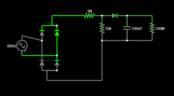
If there's a better/cheaper way to do the voltage measurement, I'm open to that too.

\$\endgroup\$
7
  • \$\begingroup\$ I don't like having to deal with so many diodes. I'd use a single diode (I'd calibrate it, if needed) and use a relaxation oscillator (with opto for isolation) where the pulse rate determines the measured voltage. This may need a calibration table, which you'll need to produce from testing using a variac (perhaps) and a true-RMS calibrated voltmeter. But it's not that complex to do. Of course, I don't know what range of voltages you want to measure. There may be a lot of still better ways, if you only need to cover a narrow range. A simple resistor divider might be enough, depending. \$\endgroup\$
    – jonk
    Commented Aug 21, 2020 at 4:40
  • \$\begingroup\$ Capacitive techniques also come to mind. In fact, now that I'm thinking of it, there are too many different "good" ideas. My mind is reeling at the number of possibilities to explore. Maybe somebody here will put down some practical knowledge and experience. If so, perhaps I'll learn yet another new trick, too. Also, here is a link to read, just in case. Similar to what you write above. \$\endgroup\$
    – jonk
    Commented Aug 21, 2020 at 4:45
  • \$\begingroup\$ An absolutely "gone crazy nuts" approach is shown here from TI. There's no way I'd go that crazy. But it shows just how serious you can become, if you want. Another, much much simpler approach, is to use transformerless power supply concepts as found here. Yet another idea among many. Pick your poison. \$\endgroup\$
    – jonk
    Commented Aug 21, 2020 at 4:51
  • \$\begingroup\$ This isn't a one-off but a piece of a larger project that may be mass produced some day, so manual testing and lookup table generation is out. Accuracy within a 0.25v or so would be acceptable. In any case, the "other ways to do it" is just a secondary point of interest. The main question is simply why the simulated voltage is so different from the calculated one. \$\endgroup\$
    – alzee
    Commented Aug 21, 2020 at 20:35
  • \$\begingroup\$ I'd like to see the full details of your thinking process and theories applied, leading to your expression that you used to make a calculation. In general, if I apply theory well I will find that my results do match simulation pretty well. You can see a non-trivial example here that makes the point. It's all about what you apply, why you apply it, where you apply it, and when you apply it. Since all I see is an expression I don't wish to make assumptions about, I'm not in a position to help much with your focus. But I know it can be done. \$\endgroup\$
    – jonk
    Commented Aug 21, 2020 at 20:44

0

Your Answer

By clicking “Post Your Answer”, you agree to our terms of service and acknowledge you have read our privacy policy.

Browse other questions tagged or ask your own question.