0
\$\begingroup\$

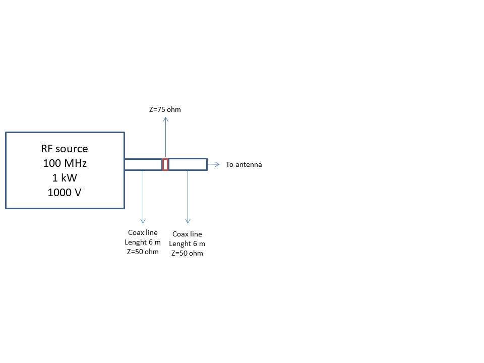
enter image description here Not being an electronics professional but face the following problem I hope you can help me. I would like to estimate the losses due to an impedance mismatch of connector used in wall-crossing of a coaxial transmission line.

Unfortunately, I do not have the experimental resources for testing the connector (with network analyzer).

Is it possible with analytical formula or with simulations?

\$\endgroup\$
1
  • \$\begingroup\$ Fix the image, show where coax screens are grounded/connected and explain what 6nnn means in your incorrectly orientated picture. \$\endgroup\$
    – Andy aka
    Commented Nov 23, 2020 at 10:26

1 Answer 1

1
\$\begingroup\$

The mismatch loss is almost certainly half of nothing, the connectors length being negligible compared to the ~2M electrical wavelength.

However, if that is an N type, be careful, 50R and 75R N types are NOT compatible and trying will either damage the female or make unreliable contact (depending on which way you try it), the centre pin geometry is different.

\$\endgroup\$

Your Answer

By clicking “Post Your Answer”, you agree to our terms of service and acknowledge you have read our privacy policy.

Not the answer you're looking for? Browse other questions tagged or ask your own question.