[UPDATE] I have answered my own question with links to experimental data and theory. Please expand on that answer if you can for the reference of future readers. Thanks for replies so far and ongoing.[/UPDATE]
I have been trying to build a current limiting rectifier on the secondary of a SMPS.
I am building this to be used with any SMPS it is a general purpose concept rather than for the specific use case I am building it for which happens to be a constant current laser driver.
There are many simple driver circuits out there, but they all waste power with a current limiting resistor or with a current sense resistor. The load resistance gets below 1 ohm in my application.
In a simple AC circuit with just a resistive load, you can use capacitive reactance to limit current with very low power loss.
I have been trying to combine this concept with a bridge rectifier to limit the current reaching the diodes to limit the current to the load. This is where the simulation breaks down.
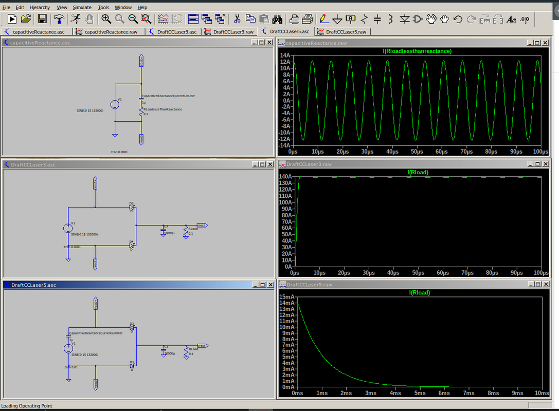
In the screenshot below I have three circuits simulated in LTSpice to demonstrate these ideas.
The first shows the basic example of just a load resistor with current limited by the reactance of the capacitor. I can change the resistance as much as I want below the reactance of the capacitor and the current in the resistor is limited by the capacitor - this is what I want. Of course, a larger resistor would dominate the limiting of current. 12A is my desired peak current as shown.
The second shows the rectifier circuit I will build, which is pretty normal and is there for reference. There is no effective current limiting and the trace shows a peak around 140A.
The third shows my attempt to merge the above two circuits, to limit the current supplied to the diodes to thus limit the current supplied to the load. But the simulation breaks down and tends to a zero current flow.
I have tried tuning the capacitor value.
I have been scratching my head over WHY it breaks down for days.
Thinking about the half cycles and polarity and current pathways etc.
In practical tests I mis-soldered and made a voltage doubler just trying things out. I'm sure there is some theory I am missing. I tried the above with a centre tapped transformer with the same outcomes.
The reason I am doing this is to save power and reduce cooling needs. What actually goes on to tend the current flow to zero and how can I make this circuit work please?
As a secondary set of ideas: I have looked into LM317 and other designs. I even thought about using comparators but the current sense resistor needs to be in series with the load which wastes power and limits current by itself with sub-ohm laser load. I can't find any designs with a current sense resistor in parallel with the load that can have a high 100 ohms to limit power use (compensated for by the gain of an op amp for comparator use.)
Theory would be helpful because I wonder why there seems to be no low wastage method to do this that doesn't need a lot of components such as current transformers.
The voltage sources in the image are all the same 15V AC at 132kHz and represent the secondary coil of a SMPS transformer.

