0
\$\begingroup\$

I am using a 12V 4-pin Noctua NF-A8 fan https://noctua.at/en/nf-a8-pwm and want to use the PWM functionality also read the rpm from it. Firstly, I went over dozens of forum discussions on a 5V 4-pin Noctua A4X10 fan which has actually kinda confused me with the fact that do we actually need an NPN transistor circuitry for the PWM pin or not. reading this thread has got a driver circuitry there

5V 4-pin Noctua A4X10 on Raspberry Pi

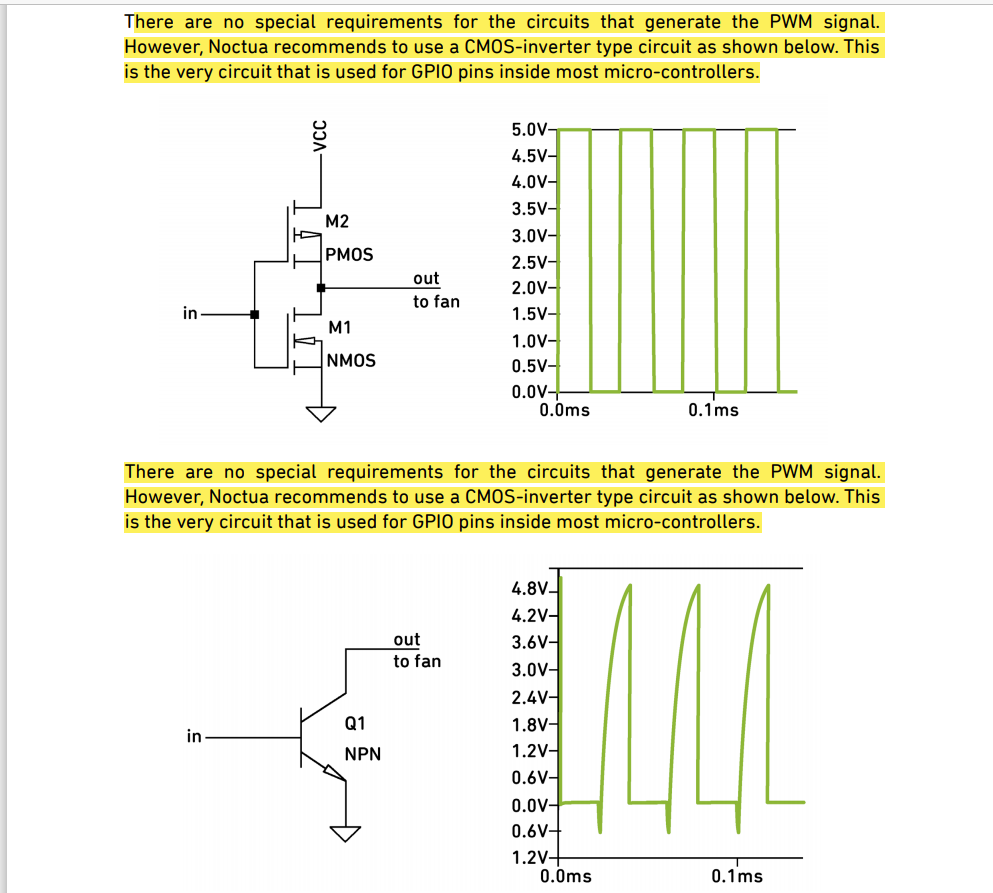
The spec pdf says it's not required but they do recommend a CMOS inverter type circuit. regarding the NPN transistor, they printed the same line which idk, of course, a big type error there.

enter image description here

Can anyone first suggest me the wiring schematic to drive a 12V fan where the supply will be given externally since pi has got 5V as max. I am talking about 12V fan variant here. I will be using either GPIO 12 or 13 for PWM pin since it has got hardware PWM and can operate in the frequecny ranges 21K - 28k as recmmonded in the spec sheet by Noctua.Similary for Fan rpm pin , I guess any gpio pin will be fine right?

As in this forum https://www.raspberrypi.org/forums/viewtopic.php?f=63&t=244194&hilit=5V+4+pin+PWM+Noctua+A4X10+on+Raspberry+Pi&sid

This guy used no driver circuitry for a 5V fan and has got the results too but again I want to reconfirm this that is it important to have a transistor there for the pwm pin if I am choosing a hardware one (GPIO 12 and 13). I dont want to use and boost converter ciruit at the moment and want to keep design simple as I can so I will power this fan externally.

Moreover my aim is to use a temperature sensor which will measure the ambient temperature and then based on its readings the fan speed will be varied using PWM. Can anyone also recommed me a decent temp sensor to for this application and how to code it using python.Sorry I am beginner level rasberry pi and linux user so need help in this project.

\$\endgroup\$
1
  • \$\begingroup\$ Connect the Noctua's yellow wire to a +12V supply, and its black wire to the supply's ground. Can you probe what voltage comes out of the blue wire? \$\endgroup\$
    – Carla H.
    Commented Mar 26, 2021 at 12:24

1 Answer 1

1
\$\begingroup\$

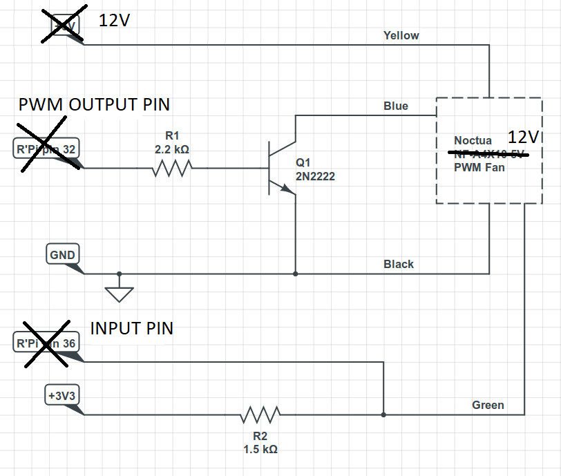
2N2222 VCE can go beyond 20V so this circuit should work, based on your intent. You can use which ever viable RPi pin you have for both the PWM output and the RPM input pins.

enter image description here

\$\endgroup\$
14
  • \$\begingroup\$ Thanks for the reply but Can I know why the PWM output which in my case is the Fan Rpm pin is used with GPIO 13? I can use any other GPIO pin too right as we want to read its speed. According to the spec sheet, I am using a 2.7k ohm resistor as recommended there for the tachometer pin, here in the schematic 1.5k seems a lesser value. Why we are still going with a transistor here, cant I just connect a resistor in series with the GPIO 12 pin? Also, these two hardware pins, are they by default capable of working in the 21kHz ranges and above, or is there any command to set it up? \$\endgroup\$
    – bh96
    Commented Mar 26, 2021 at 12:40
  • \$\begingroup\$ Which GPIO will you use for the RPM reading? Which GPIO will you use for the fan's PWM input? The GPIO set on the pic are just placeholders based on your stated GPIO preferences. You can freely change those GPIOs to whatever you intend to use. 2.7k or 1.5k it does not matter as you're only seeing sub-1kHz transition on this pin... in fact, the datasheet specified an 80Hz example which can be considered low frequency. The resistor in Q1's base is there for current limiting and safety purposes. \$\endgroup\$
    – Carla H.
    Commented Mar 26, 2021 at 12:54
  • \$\begingroup\$ For eg I can use GPIO 16 for Rpm and GPIO 12 or 13 for the PWM input. as I did understood the use of resistor for each PWM and RPM pin path when connected to the GPIO pins in Rasberry pin but here I want to know whether Q1 ( transistor) is necessary for the PWM pin. the spec said no special requirements necessary but they recommend too. Moreover, I read 50Hz there using 2.7Khz, why I can't read higher frequencies? yes in the example they show an 86Hz which I don't get why this low or maybe just for demonstration purpose \$\endgroup\$
    – bh96
    Commented Mar 26, 2021 at 13:02
  • \$\begingroup\$ Yes, Q1 is necessary for the PWM pin. Q1 enables pulling the blue pin low to GND without making the current pass through your RPi pins (and damaging it). Perhaps you need to multiply 50Hz by 60 to get the instantaneous RPM. \$\endgroup\$
    – Carla H.
    Commented Mar 26, 2021 at 13:12
  • 1
    \$\begingroup\$ I still highly recommend using Q1, as it prevents your RPi pin from sinking too much current vs if you decide to do away with R1 and Q1. \$\endgroup\$
    – Carla H.
    Commented Mar 26, 2021 at 14:06

Your Answer

By clicking “Post Your Answer”, you agree to our terms of service and acknowledge you have read our privacy policy.

Not the answer you're looking for? Browse other questions tagged or ask your own question.