1
\$\begingroup\$

I have a biosensor. It's resistivity changes while sensing the analyte I want. Resistivity of biosensor is around 10 Ohms.

I normally use Keithley 2400 sourcemeter for experiments. I apply a constant voltage across the biosensor, then measure the resulting current using same probes.

I need to make this amperometric measurements using microcontroller. I'm applying same potential using pwm after filtering and buffering.

My intention is to apply a constant voltage to biosensor (0.5V), have a small shut resistors connected to biosensor in series, and measure the voltage over the shunt resistor using uC's ADC.

But since both biosensor and shunt resistor have small values, it drains a lot of current which microcontroller is not able to handle.

The voltage that I'm applying goes directly to zero.

What should I do to be able to measure the current in this system? I have been thinking to use instrumentations amplifiers, but I still have the same main problem, sinking huge current to ground which makes the applied potential zero.

\$\endgroup\$
6
  • \$\begingroup\$ How much does the resistance of this sensor vary over the range of values you wish to measure? \$\endgroup\$
    – Phil Frost
    Commented Jan 21, 2013 at 14:16
  • \$\begingroup\$ It changes only around 3 to 5 Ohms. \$\endgroup\$
    – asibio
    Commented Jan 21, 2013 at 14:32
  • \$\begingroup\$ I don't have time to write a full answer, but this should be a big enough change that you can pass a much smaller current through your sensor, then amplify it and still have a good signal-to-noise ratio. "wheatstone bridge" is another direction to research. \$\endgroup\$
    – Phil Frost
    Commented Jan 21, 2013 at 14:41
  • \$\begingroup\$ @PhilFrost - That assumes you don't need that current for excitation/chemistry reactions/whatever. Actually, that's a good question. \$\endgroup\$ Commented Jan 21, 2013 at 14:53
  • \$\begingroup\$ @asibio - Does the device need the ~50 mA (0.5V excitation) to work, or was that just so you got a easy-to-measure voltage drop across the device? \$\endgroup\$ Commented Jan 21, 2013 at 14:53

1 Answer 1

2
\$\begingroup\$

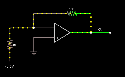
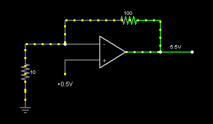
Since you don't need a lot of current, (0.5V/10Ω = 50 mA), I would say using a fairly chunky op-amp as a transimpedance amplifier would do the job.
enter image description here

enter image description here

The output will be: \$V_{out} = I_{load} * R_{feedback} + V_{inPositive}\$

The first schematic has the advantage that the output has no offset. However, you need a negative voltage rail.
The second version does not require a negative voltage rail, but the output has a additional 0.5V offset.

In both circuits, the op-amp needs to be able to source the current that flows through the biosensor. With a 10Ω nominal sensor, and 0.5V, this is 50 mA, which is pretty significant, so you will need a pretty chunky op-amp. However, you would likely wind up needing a similar device for the current-source and instrumentation amp design, so there is no real advantage there.

Lastly, assuming your sensor does not go to 0Ω, it would probably be a good idea to do some offset subtraction and scaling of the output of the transimpedance amp so you're using your full ADC range.
If you can get me some more information on your system, I can probably help with that.


Edit: Phil Frost asked a question the the comments to the OP that brought up the question of whether the 50 mA current through the sensor is actually needed for it to operate correctly, or whether it was just so the circuit would produce an easy-to-measure voltage drop.

If it's just make the circuit generate a voltage drop that's easy to measure, there are other circuit topologies that would be easier to implement, with a smaller load current.


Further Edit:

Actually the sensor/chemistry reaction doesn't need a certain voltage across it. I'm not sure if it was good choise or not but I picked up 0.5 V just to have a reasonable voltage drop.

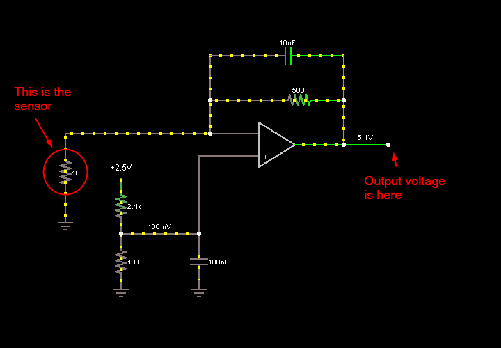
In that case, I would drop the excitation voltage to ~0.1V. This would give you a load current of ~10 mA, which is well within the range of most op-amps, while not being so small that noise becomes a significant consideration.
Furthermore, I would probably use the second topology from above, as with that layout the precision reference voltage does not need to be able to supply a significant ammount of current, which means you could use a more common voltage reference, and a voltage divider to generate your 0.1V reference.
To maintain a decent amount of gain, you will need to increase the feedback resistor.

Lastly, I would add some capacitance across the feedback resistor, to prevent the possibility of the system oscillating. Since this is a bio-feedback thing, you're not going to have much in the way of high-frequency signals in the source, so we can roll-off the system at a few hundred Hz to a few Khz without too much issue.

We then get something like:
enter image description here

You will likely need to adjust the values to work (I just pulled the value of the feedback capacitor out of my posterior, for example), but it should be a good start.

\$\endgroup\$
7
  • \$\begingroup\$ Thank you for the nice detailed answer 'Fake Name'. Actually I don't need certain amount of voltage across the sensor to get it work. Can you suggest better circuit topologies to be able to measure the voltage increasement across the biosensor. Thanks. \$\endgroup\$
    – asibio
    Commented Jan 21, 2013 at 15:30
  • \$\begingroup\$ @asibio - updated answer \$\endgroup\$ Commented Jan 21, 2013 at 15:49
  • \$\begingroup\$ I didn't quite get how I could integrate this circuitry with the sensor and microcontroller. Could you explain that? \$\endgroup\$
    – asibio
    Commented Jan 21, 2013 at 16:28
  • \$\begingroup\$ @asibio - updated the second image \$\endgroup\$ Commented Jan 21, 2013 at 16:55
  • \$\begingroup\$ Click through the images. It will take you to an interactive simulation of the circuit. \$\endgroup\$ Commented Jan 21, 2013 at 16:56

Your Answer

By clicking “Post Your Answer”, you agree to our terms of service and acknowledge you have read our privacy policy.

Not the answer you're looking for? Browse other questions tagged or ask your own question.