0
\$\begingroup\$

I'm building an Arduino switch for two different signals and I'd be very grateful if you can revise the schematic and tell me if there's something wrong or if something can be improved.

In the schematic you can see two switches (representing two different Arduino GPIO pins) with a 1k serial resistor to limit the current according to Arduino's datasheet.

The labels represents an unknown external circuit. The only thing I can say about it it's that the BJT transistor is connected to a low-power high-frequency (~870kHz) circuit, and the MOSFET is connected to a 5V high-current (~3A) circuit.

The circuit should be on if the Arduino isn't placed (thus open circuit on GPIO pins), that's why I placed a 10k pull-up on the base of the BJT transistor.

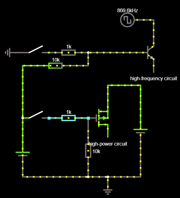
Schematic

\$\endgroup\$
8
  • \$\begingroup\$ 50 mΩ on 5 V will give a current of 100 A so I suspect you have an error there. What are you really trying to achieve with this circuit? \$\endgroup\$
    – Transistor
    Commented Apr 12, 2021 at 21:08
  • \$\begingroup\$ @Transistor it's just for the simulation, instead of 50mΩ there's connected the 5V-3A circuit \$\endgroup\$ Commented Apr 12, 2021 at 21:09
  • \$\begingroup\$ Well why not simulate properly? You didn't answer my second question which I asked because whatever you're trying to achieve it is very unlikely that this is the way to do it. \$\endgroup\$
    – Transistor
    Commented Apr 12, 2021 at 21:12
  • \$\begingroup\$ @Transistor that circuit it's a PCB which I don't have access to the schematic, I just made that circuit to see it there's voltage coming out of the transistors \$\endgroup\$ Commented Apr 12, 2021 at 21:15
  • \$\begingroup\$ OK, take the lower switch and MOSFET. What's your understanding of how that should work? \$\endgroup\$
    – Transistor
    Commented Apr 12, 2021 at 21:18

1 Answer 1

0
\$\begingroup\$

You can delete both 1 K resistors, because in both cases there is a 10 K resistor to limit the current.

The schematic just changes, so there goes one question.

What is the logic polarity for each circuit? Each GPIO pin has two states. What is the desired circuit action for each state of each GPIO pin?

\$\endgroup\$
2
  • \$\begingroup\$ About deleting the 1k resistors... are you sure? According to this video he neded both 1k and 10k. \$\endgroup\$ Commented Apr 13, 2021 at 15:32
  • \$\begingroup\$ About the logic: the switch will be replaced with a GPIO pin. It can be HIGH, LOW or Hi-Z (if the Arduino isn't plugged into the socket). I don't care if HIGH mean OFF or vice versa, but I just want the whole circuit ON while Hi-Z. \$\endgroup\$ Commented Apr 13, 2021 at 15:37

Your Answer

By clicking “Post Your Answer”, you agree to our terms of service and acknowledge you have read our privacy policy.

Not the answer you're looking for? Browse other questions tagged or ask your own question.