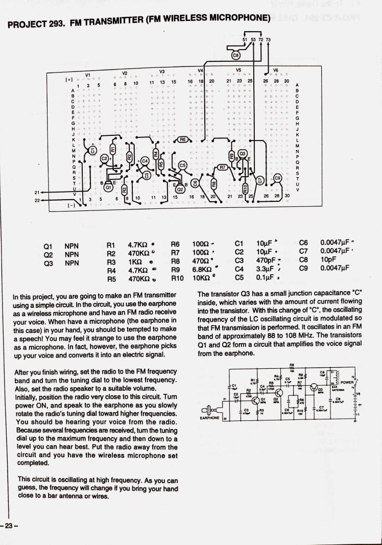
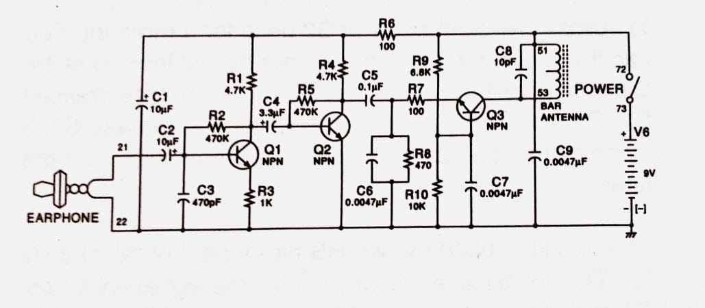
I have been tinkering with AM transmitters but now I would like to build and understand FM transmitter circuits. I came across this circuit in a electronics projects book but it does not explain at all how the circuit works. I would love if somebody could explain every part of the circuit.
-
1\$\begingroup\$ Without getting into heavy electronics theory, the description posted explains the ‘trick’ of how the FM modulation works. Q1 and Q2 are simply an amplifier for the audio. What specifically do you want to know? \$\endgroup\$– KartmanCommented May 22, 2021 at 23:05
-
\$\begingroup\$ I want to know the heavy electronics theory. \$\endgroup\$– AndrealphusCommented May 22, 2021 at 23:22
-
3\$\begingroup\$ That circuit is unlikely to work - there is no feedback for Q3 to oscillate. A ferrite bar antenna would not be used at FM frequencies it's inductance would be too high. \$\endgroup\$– Kevin WhiteCommented May 22, 2021 at 23:44
-
1\$\begingroup\$ There's a zillion variations one the same theme - just Google and see what I mean. Try Google talking electronics fm wireless. If you want to know the electronics theory, then there's free online university electronics courses. You're going to need at least first year circuit and transistor theory. We're not going to be able to teach you enough in a couple of paragraphs on a Q & A site. If you could do this, then many of us could've saved 3-4 years of our lives not going to university! \$\endgroup\$– KartmanCommented May 23, 2021 at 3:34
-
\$\begingroup\$ An evening’s study of Horowitz and Hill’s The Art of Electronics will explain the basics of transistor amplifier circuits better than I could, and having a copy on your bookshelf brings much prestige. \$\endgroup\$– FrogCommented May 23, 2021 at 10:06
2 Answers
I'm not an FM guru but I'll have a stab, perhaps some others can refine my answer.
Since you have some familiarity with AM amplifiers, Q1 and Q2 may be reasonably familiar to you, these simply amplify the signal from the earphone which is acting as a microphone. As an aside, a modern-day 32-ohm headset should work in this way, although the microphones that are typically used with PCs/smartphones require a DC bias voltage that this circuit doesn't supply, although a 10k resistor between (21) and +9 should do the trick.
The interesting part of the circuit is C8 and the bar antenna, which together form an LC circuit. Depending on the inductance of the bar antenna (which will be a number of turns of wire around a ferrite bar), the LC will tend to oscillate at a certain frequency. This needs some form of energy input to get it to resonate though, and this is provided by Q3. The emitter of Q3 has a path to ground through R7 and R8, and the base is biased to around 6V by R9,10. Therefore Q3 will tend to draw some base-emitter current to pull the emitter up to 600mV below the base voltage, and this will draw some current through the LC. As the LC oscillates, a small increase in the voltage at (53) will increase the current flowing through R7,8 and so the emitter voltage increases, causing the base-emitter voltage to decrease and thus reducing the collector-emitter current that Q3 will allow to flow. This effect is more significant at higher frequencies because C7 will act to maintain the base voltage. The net effect is that the current that Q3 allows to flow has a phase angle that's ahead of the resonance of the LC and so it pumps in a little energy during each cycle.
The audio signal is coupled in to R7,8 via C5 and so its AC component causes the voltage on Q3 emitter to fluctuate and this in turn alters the current that's flowing through the LC. Intuitively, if the current increases and the LC oscillation needs to swing down to a slightly lower voltage before Q3 starts to inject energy then the frequency will drop, and conversely if the current decreases then the frequency will increase.
Conversely, if the DC current through the inductor increases then the inductance may decrease, particularly if the inductor is near to saturation, so an increased current would result in a reduced inductance and therefore a higher resonant frequency.
The two effects I've described work on opposite directions and so I've be guessing which one is dominant in this circuit.
The critical stage of your transmitter is the rf oscillator with transistor Q3. In my experience a coil for the fm band about 100 MHz doesn't have a ferrite nucleus inside: its nucleus is the air. The only use you may do of the ferrite bar is to form the coil. Turn around it about 8 turns of copper wire 1 mm diameter and then take the ferrite apart. You can slightly modify the frequency of transmission by spacing the turns of the coil. If Q3 is unable to oscillate, try to connect a small capacitor (5 or 8 pF} between C and E. Use for Q3 a BJT with a high cut off frequency like a BF199. An useful instrument to adjust the oscillator would be a dip meter.
-
1\$\begingroup\$ The dashed double line next to the inductor typically indicates a ferrite core, but I agree that an air core could also be used. \$\endgroup\$– FrogCommented May 23, 2021 at 3:09


