0
\$\begingroup\$

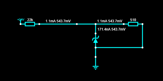
I am using a 4.7V (1N4732A) Zener diode to regulate input voltage from 24V to 5V for an Arduino input. Everything works perfectly. I am not really sure how.

Which current parameter in the datasheet should I consider when using a Zener diode for voltage regulation?

enter image description here

\$\endgroup\$
4
  • \$\begingroup\$ What does the picture explain other than that you have too much load current through the 510 ohm resistor or, too much resistance in the 22k resistor? \$\endgroup\$
    – Andy aka
    Commented Jun 30, 2021 at 12:26
  • \$\begingroup\$ @bcicek: You could remove the Zener diode from your diagram and you would still get about 0.54 volts at the junction of the 22k resistor and the 510 ohm resistor. You have a voltage divider that makes 0.54 volts with a Zener diode in parallel with part of the divider. \$\endgroup\$
    – JRE
    Commented Jun 30, 2021 at 12:31
  • 1
    \$\begingroup\$ I am using a ... Zener diode to regulate input voltage from 24V to 5V for an Arduino input. For us EEs, "input voltage" means that you only want to sense that the 24 V is there (or not) and that you do not intend to power the Arduino like this as that will not work. Even if you remove the 510 Ohm resistor that is now preventing your circuit from working as you want it to. I think some studying is required so that you learn more about shunt regulators. And if you do want to power that Arduino from 24 V, use a voltage regulator IC or module. \$\endgroup\$ Commented Jun 30, 2021 at 15:18
  • \$\begingroup\$ Are you SENSING the 24V or hoping to POWER something? Without the 510R you will get about I= V/R = (Vin-Vzener)/ 22k ~= 0.9 mA. Fine for sensing. No good for power. | Remove the 510 Ohm in yuour simulation and see the result. \$\endgroup\$
    – Russell McMahon
    Commented Jul 16, 2021 at 22:51

1 Answer 1

1
\$\begingroup\$

A Zener diode has three datasheet values to consider; one, is a package-related power limit; second, a recommended bias current. Third, is the dynamic impedance (the equivalent resistance for small signals when under bias). Bias current, in the above circuit, is nil, so it isn't really regulating at 4.7V at all.

Accuracy of the voltage at the Zener cathode has two terms: one is the unit-to-unit variation allowed by the manufacturer, the other is the current variation (if any) drawn by the Zener times the dynamic impedance of the diode.

For a 4.7V Zener, a 0.5V terminal voltage indicates the bias current is not sufficient to achieve regulation. 1N4732A is a typical 4.7V Zener diode, and at 53 mA bias (24V source and 360 ohm, 1W resistor) its equivalent resistance is about 8 ohms.

That makes it a good regulator of its output voltage, since the fluctuations of the 24V supply only connect through higher (360 ohm) resistance than the 8 ohm value. It also wastes quite a lot of electrical power, which is why the 1W rating of the resistor is important.

That diode can, with air cooling, take up to 1W, so the bias current could be raised to 200 mA, allowing zero to 150 mA delivered to the load, while remaining a 'good' regulator. That would mean a pullup resistor of about 100 ohms, rated for 4W, however.

\$\endgroup\$

Your Answer

By clicking “Post Your Answer”, you agree to our terms of service and acknowledge you have read our privacy policy.

Not the answer you're looking for? Browse other questions tagged or ask your own question.