4
\$\begingroup\$

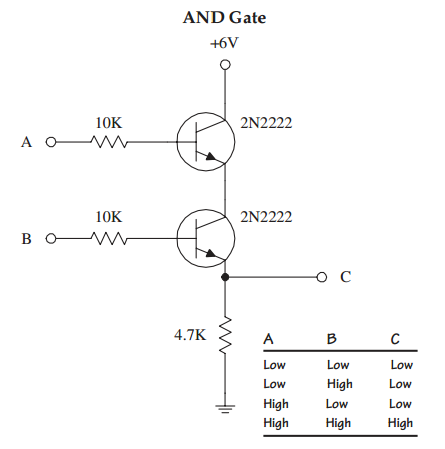
Looking at this circuit (first circuit):

circuit diagram

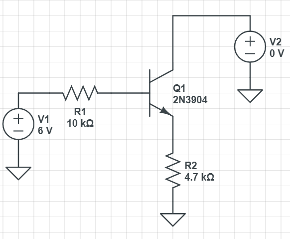
Choose a value for V2 between 0V and 10V. Then how could we know the IB, IC, IE, VB, VC, VE? Can we solve it by hand (by hand means the value IB, IC, IE, VB, VC, VE no need to be exact, but in general, it makes sense, using vol-amp characteristic curve of BJT is allowed...) or must we use a simulator?

I try one example, say V2 = 0V. I thought there is a current goes from V1 to R1 to base to emitter to R2 to ground. But when I use simulation, I find that there is no current goes through R2, there is a current goes from R1 to base to collector to V2 to ground. This is very different than I thought.

And then increase V2 to 0.1V 0.2V 0.3V in simulator ...there are a lot of things happen that I can't think of one way to solve this by hand (with value of V2 randomly chosen). Please help me out.

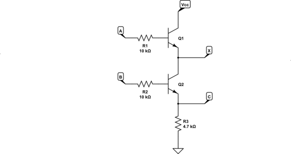
My ultimate purpose for this is I want to solve this circuit (second circuit):

enter image description here

Let VA = 0V or 6V and VB = 0V or 6V, then solve for all currents and voltages in the circuit. I think I have to understand the first circuit then I am able to solve the second circuit.

\$\endgroup\$
3
  • \$\begingroup\$ Do you understand how an emitter follower works? \$\endgroup\$
    – D.A.S.
    Commented Aug 1, 2021 at 16:59
  • \$\begingroup\$ Not yet, I still think about it too \$\endgroup\$
    – Dat
    Commented Aug 1, 2021 at 17:02
  • \$\begingroup\$ Your circuit is not equivalent. In particular if A is low the voltage at the emitter of the top transistor will not be pulled to 0V as your circuit implies. Try adding a diode in series with your ideal voltage source. \$\endgroup\$ Commented Aug 1, 2021 at 17:47

3 Answers 3

5
\$\begingroup\$

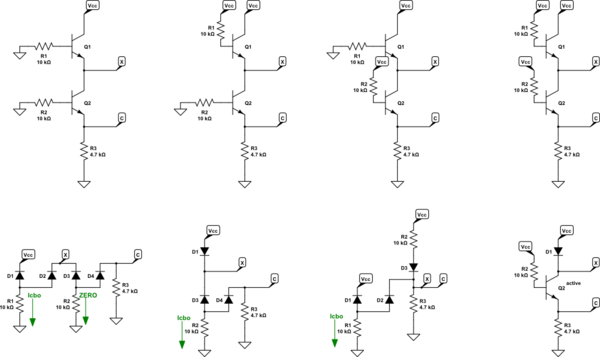
I'll focus on the poor AND circuit:

schematic

simulate this circuit – Schematic created using CircuitLab

There are four conditions, as you've suggested. Take each one in turn, given your statement about \$V_{_\text{CC}}=6\:\text{V}\$ and nominally for initial analysis purposes, \$LO=0\:\text{V}\$ and \$HI=6\:\text{V}\$. (In all cases, while we may not know the exact value for \$X\$, we do know that it cannot be below ground nor above \$V_{_\text{CC}}\$.)

Before I continue, there is a BJT parameter you can find on datasheets: \$I_{_\text{CBO}}\$. This is the collector cutoff current. For example, from this old datasheet on the 2N2222 you can see the value at room temperature and with \$50\:\text{V}\$ of reverse CB voltage, \$I_{_\text{CBO}}\le 10\:\text{nA}\$ and at \$150^\circ\:\text{C}\$ it rises to \$I_{_\text{CBO}}\le 10\:\mu\text{A}\$ (1000 times higher.) Either way, these are very tiny currents. For below, let's just assume \$I_{_\text{CBO}}= 50\:\text{nA}\$. (In practice and in Spice it will not be that high.)

  1. \$A=LO\$ and \$B=LO\$: \$Q_1\$ is off, regardless of \$X\$, and therefore the collector/base junction is reverse-biased by about \$6\:\text{V}\$ and we can assume only a small \$I_{_\text{CBO}}\$ via \$R_1\$, meaning the base voltage will be about \$500\:\mu\text{V}\$. Emitter current is essentially zero. \$Q_2\$ is off. So \$Q_2\$'s base is hugged tight to ground and should be very close to it. As there is no emitter current in \$Q_1\$ there cannot be any collector or emitter current in \$Q_2\$. So \$R_3\$ pulls the output down almost exactly to ground. Output impedance is \$R_3\$.
  2. \$A=HI\$ and \$B=LO\$: \$Q_1\$ is active. But \$Q_2\$ is off. so we expect at most \$I_{_\text{CBO}}\$ in \$Q_2\$. That current has to come from \$Q_1\$'s emitter. But as only \$\frac1{\beta+1}\$ of it comes via \$R_1\$, we can pretty much say the base of \$Q_1\$ is also at \$6\:\text{V}\$. It's emitter will be about \$V_T\cdot\ln\left(\frac{I_{_\text{CBO}}}{I_{_\text{SAT}}}\right)\$ or perhaps as much as a few hundred millivolts across the BE junction of \$Q_1\$. So we'd expect \$Q_2\$'s collector to be within a few hundred millivolts of \$V_{_\text{CC}}\$. That still doesn't mean there's any emitter current in \$Q_2\$, as it is off. So, again, \$R_3\$ pulls the output down almost exactly to ground. Output impedance is \$R_3\$.
  3. \$A=LO\$ and \$B=HI\$: \$Q_1\$ is off. So its emitter current is basically zero. But \$Q_2\$ is active, now. While there's no \$Q_2\$ collector current, you do have two resistors present. So the emitter current (which is also the base current) is \$\frac{V_{_\text{CC}}-V_{_\text{BE}}}{R_3+R_2}\$ and, after multiplying that current by \$R_3\$, gives about \$1.7\:\text{V}\$ at the output. This is not really \$LO\$ nor is it really \$HI\$. So this is probably a bad AND gate. Output impedance is about \$R_3\mid\mid R_2\$ (though there may be a very slight bit of Shockley diode stuff going on, it's not important given these resistor values.)
  4. \$A=HI\$ and \$B=HI\$: Both \$Q_1\$ and \$Q_2\$ are now active and now there can be some emitter current from \$Q_1\$ into \$Q_2\$'s collector. So in this case, the emitter current of \$Q_2\$ is \$\frac{V_{_\text{CC}}-V_{_\text{BE}}}{R_3+\frac{R_2}{\beta+1}}\$ and, after multiplying that current by \$R_3\$, gives about \$5.2\:\text{V}\$ at the output. Again, this isn't exactly \$LO\$ nor is it really \$HI\$. But it's perhaps close enough to \$HI\$ to be tolerable. Output impedance is closer now to \$\frac{R_2}{\beta+1}\$, which is low enough to be useful.

Assuming \$\beta\approx 200\$:

$$\begin{array}{c|c|c} \text{A} & \text{B} & \text{C (volts)} & \text{C (}\Omega\text{)}\\\hline {\begin{smallmatrix}\begin{array}{c} 0\:\text{V}\\ 6\:\text{V}\\ 0\:\text{V}\\ 6\:\text{V} \end{array}\end{smallmatrix}} & {\begin{smallmatrix}\begin{array}{cc} 0\:\text{V}\\ 0\:\text{V}\\ 6\:\text{V}\\ 6\:\text{V} \end{array}\end{smallmatrix}} & {\begin{smallmatrix}\begin{array}{c} 0\:\text{V}\\ 0\:\text{V}\\ 1.7\:\text{V}\\ 5.2\:\text{V} \end{array}\end{smallmatrix}} & {\begin{smallmatrix}\begin{array}{c} 4.7\:\text{k}\Omega\\ 4.7\:\text{k}\Omega\\ 3.2\:\text{k}\Omega\\ 50\:\Omega \end{array}\end{smallmatrix}} \end{array}$$

In short, I'd say that this isn't really a good AND gate.

Here's the four cases. Top row, left to right, showing all the connections, respectively to the cases above. Bottom row, left to right, their equivalent cartoons.

schematic

simulate this circuit

\$\endgroup\$
15
  • \$\begingroup\$ A lot more questions: at the first case A = LO, B = LO, how do you know the emitter current of Q1 is essentially zero? I thought ICBO = 50 uA when the emitter is open (to ensure IE =0) , but in this circuit, emitter of Q1 is not open. \$\endgroup\$
    – Dat
    Commented Aug 2, 2021 at 7:02
  • \$\begingroup\$ @Dat There's nothing to cause an emitter current in Q1. There is Icbo from collector to base. But that's not going to trip over to the emitter, not for any reason. So tell me: from what exact mechanism do you see emitter current in Q1? Who is sinking that current, and how? How does it source in the first place? There's no Q1 emitter current in case 1. \$\endgroup\$
    – jonk
    Commented Aug 2, 2021 at 7:23
  • \$\begingroup\$ At second case, how do you know Q1 is active when Vx is not known? I am so confused with a lot of things can happend in this circuit. \$\endgroup\$
    – Dat
    Commented Aug 2, 2021 at 7:23
  • \$\begingroup\$ @Dat In case 2 you can almost imagine that Q1 is "diode-connected" if you just stop worrying about R1. If R1=0 then it is diode-connected and it's just a flurgen diode from Vcc. So of course the emitter is "hot." The fact that there's a resistor in the base path doesn't much alter this fact. The Q1 emitter is hot in case 2. Its emitter can, if asked, source current. Can't you see that fact? \$\endgroup\$
    – jonk
    Commented Aug 2, 2021 at 7:34
  • \$\begingroup\$ I don't know exactly, there are so many mechanisms about BJTs and this makes me confused. I feel like we can't predict what will happen, we must do the experiments to have experiences then we can predict other circuit after \$\endgroup\$
    – Dat
    Commented Aug 2, 2021 at 7:34
4
\$\begingroup\$

I try one example, say V2 = 0V. I thought there is a current goes from V1 to R1 to base to emitter to R2 to ground. But when I use simulation, I find that there is no current goes through R2, there is a current goes from R1 to base to collector to V2 to ground.

It's a NPN transistor, so both the base-emitter junction and the base-collector junction are a PN junction. So, under the right conditions, current can flow from base to collector as you've seen.

Below is a simplified version of your schematic to better illustrate why. The 2 PN junctions are replaced with diodes and the 0V V2 with ground. (because a 0V DC supply is equivalent to ground).
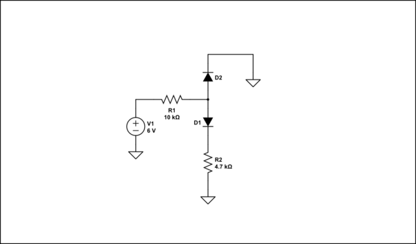
schematic

simulate this circuit – Schematic created using CircuitLab

Current can flow trough D2 straight to ground. The voltage at the anode will be about 0.6V above ground (D2's forward voltage). Any current flowing trough D1 and R2 causes a voltage drop in R2, which lifts D1's cathode voltage. Since it's anode is clamped at 0.6V by D2 there's not enough forward voltage to keep D1 conducting. Thus the bulk of the current will flow trough D2.

Note that this is a special situation, caused by the resistance in series with the emitter and forcing the collector voltage low enough, not something you'll see in actual circuits.


EDIT:

As you explain, I understood when V2 = 0. But how about V2 = 0.1V ; 0.2V ; 0.3V ; 0.4V...?

It's just as simple for other V2 voltages. Say V2 = 0.2V. Now D2's cathode is at 0.2V, so it's anode will be at around 0.8V (0.2 + D2's forward voltage). Now current can flow trough R2 until the voltage drop over R2 reaches approximately 0.2V (about 42μA). From then on D1's forward voltage will start being pinched off again. The rest of the current will flow trough D2.

Since we know the diode's anodes are at 0.8V you can calculate the current trough R1, subtract the 42μA going trough D1/R2, and arrive at the current trough D2.

You will find that if you keep increasing V2's voltage, at some point there won't be enough forward voltage for D2 or D2 becomes reverse biased and current can no longer flow in that direction.

(A major caveat to keep in mind is that a diode's forward voltage depends somewhat on the current trough the diode. For the very tiny currents we're talking about the forward voltage could be a bit less then 0.6V. Remember that when you're trying things out.)

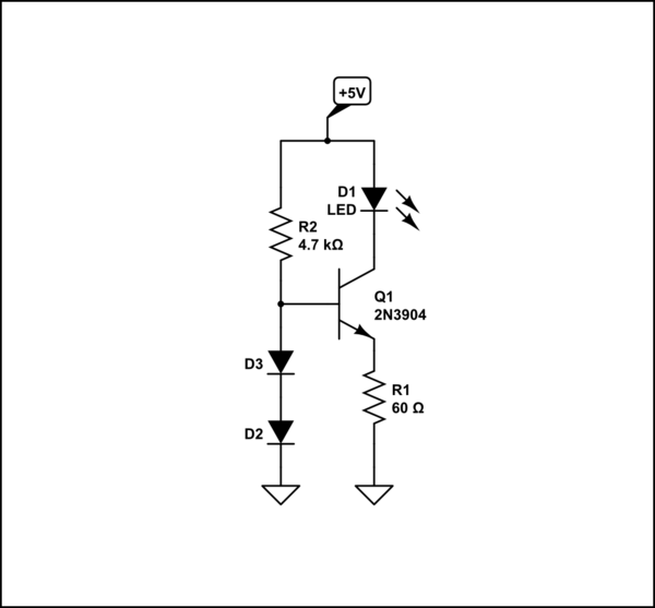
This technique of pinching off forward voltage can actually be used. For example, here's a simple current limiting circuit:
schematic

simulate this circuit

D2 and D3 will keep the base voltage at approximately 1.2V. A small base-emitter current will flow, allowing a much larger collector-emitter current to flow which lights the LED. Both the B-E and C-E current will flow trough R1 to ground, causing a voltage drop in R1 which lifts the emitter voltage. When the drop over R1 reaches around 0.6V the B-E will start being pinched off. So current is limited to around 10mA.


As for your second circuit, it pretty much functions as you said. Applying 6V to the base resistors of both transistors allows base-emitter current to flow in both transistors. This allows collector-emitter current to flow in both transistors and current can flow from the +6V supply to point C. Apply ground to any of both base resistors and base-emitter current can no longer flow in that transistor and thus no more collector-emitter current.

The 4.7K resistor here is simply a pull-down to keep point C at a low level when any or both transistors are off.

\$\endgroup\$
5
  • \$\begingroup\$ As you explain, I understood when V2 = 0. But how about V2 = 0.1V ; 0.2V ; 0.3V ; 0.4V...? Is there a rule to know the directions of all currents in the circuit in each case? With second circuit, I understand the idea of the circuit like you said but I want to know all the voltage and current at any point in the circuit. For example: what is the voltage at the point between two transistors when VA = VB = 6V? \$\endgroup\$
    – Dat
    Commented Aug 2, 2021 at 3:59
  • \$\begingroup\$ @Dat Updated the answer. \$\endgroup\$ Commented Aug 2, 2021 at 8:03
  • \$\begingroup\$ @Dat increase R2? Do you mean at what voltage for V2 will current stop flowing from base to collector? \$\endgroup\$ Commented Aug 2, 2021 at 18:47
  • \$\begingroup\$ Oh I am sorry, I mean V2 \$\endgroup\$
    – Dat
    Commented Aug 2, 2021 at 23:30
  • \$\begingroup\$ When V2 = 0.1 V 0.2V ....The transistor works very different from what I know. At which voltage should V2 be increased to see the transistor functioning, like we can have Ic = 100*IB normally? \$\endgroup\$
    – Dat
    Commented Aug 3, 2021 at 1:55
0
\$\begingroup\$
  • the Com.Collector or Emitter follower which is a current buffer… Imagine it as an impedance amplifier in both directions with a 600 mV drop when Vbe is forward biased.

So you have an attenuating switch with fig1

When input is high, R1= 10k /hFE and load = 4.7k minus 600 mV so let hFE=100 and emitter sees 10k/100=100 ohms pulling up with 600 mV drop and 4700 ohm load and it is a logic “1”. so you get what voltage?

Then for the AND gate the top switch must give a follower voltage with the B-E diode drop ~ 600 mV drop and this only reduces the Voh or V output-high by that much. But still a logic “1” when high.

So the output will drop 2 diode drops from V2 when both NPN’s inputs are high at 6V. E.g. if V2=5V Voh=5-1.2= 3.8V. For TTL Logic Voh>2V = “1”. This means to satisfy TTL logic, the V2 must be at least 2V+1.2V = 3.2V

Although I know that all TTL thresholds are 2 diode drops at input or from 1.2 to 1.3V so the 2V requirement for Voh is for noise margin of the difference.

The other fact is for Ic =1mA Vbe= ~ 600 mV and rises to 700mV ~ 10 mA or so depending on size of transistor and less with lower current, so Voh/4k7 changes somewhat with V2, so there is a small change there. This comes from standard diode characteristics which vary exponentially with current until saturated at 0.7V then bulk resistance of the BE junction or diode limits the rise of voltage with current above 1mA.

\$\endgroup\$

Your Answer

By clicking “Post Your Answer”, you agree to our terms of service and acknowledge you have read our privacy policy.

Not the answer you're looking for? Browse other questions tagged or ask your own question.