1
\$\begingroup\$

I have a Ryobi battery that I'd like to charge from 12V instead of 230V. The charger comes with a power supply that outputs 36V 1.7A, so I thought I could easily replace this with at step-up boost converter with the same specifications.

I am using this converter - I think it should be fully capable of the task.

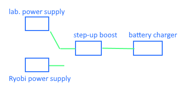
Like this:

schematics

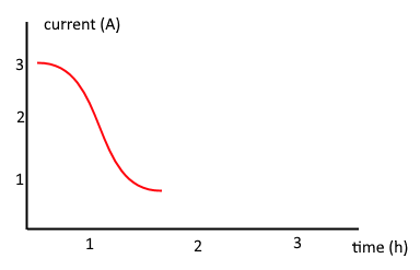
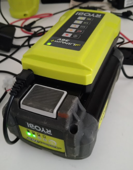
When connected to my lab power supply, it almost seems to work. On the battery there are 4 steps to indicate charge (see picture.) When it charges one step, the current output on the lab supply goes from 3A to 0.7A in about an hour and then the charging seems to stop.

I imagine this is because the battery has four cells, and the current drops to "fill the cell entirely" before moving on to the next. (Just a guess.)

lab power supply current indicator

The problem is that charging seems to "hang" here.

If I compare with the 230V power supply, I see that the charging voltage is slightly higher at this state (38.3V.) If I adjust the boost converter to this voltage, then suddenly the charger returns to using about 2A, and the charging continues.

My thought was that since I only replaced the 230V power supply, I would not get into trouble that would possibly destroy the battery - is that true?

What can I do to make the charging "run" all the way?

enter image description here

\$\endgroup\$
7
  • \$\begingroup\$ Is the Ryobi battery a Lithium? If so (likely) have you studied the charging cycle for that type of battery? \$\endgroup\$
    – jonk
    Commented Aug 7, 2021 at 6:59
  • \$\begingroup\$ Yes, I assume so since it says Lithium on the outside. But wouldn't the charger handle the charging cycle specifics if the boost converter just supplies enough power? I assume that there is no "logic" in the wall transformer (230V power supply)? \$\endgroup\$
    – Bjm
    Commented Aug 7, 2021 at 7:03
  • 1
    \$\begingroup\$ I think there is logic involved in any good lithium charger. And the required voltage you measured may be only for the initial phase of that. Later on, it may require a different overhead voltage. But I'm no expert, either. So I won't say more. I just think your approach may be a little over-simplistic. Finally, I can't say I completely understand your approach. So I may be missing a detail that you are not missing. \$\endgroup\$
    – jonk
    Commented Aug 7, 2021 at 7:06
  • \$\begingroup\$ ”I imagine this is because the battery has four cells, and the current drops to "fill the cell entirely" before moving on to the next (just a guess)?” No, absolutely not. \$\endgroup\$
    – winny
    Commented Aug 7, 2021 at 7:39
  • \$\begingroup\$ Yes, it was just a guess. Do you know, how it actually works? I'm curious to understand... \$\endgroup\$
    – Bjm
    Commented Aug 7, 2021 at 8:04

2 Answers 2

0
\$\begingroup\$

Do your bench power supply and your boost converter have enough power output? both of them should have enough current margin to allow brief "spikes" in current drawn by the battery charger.

The fact that you matched the "36V 1.7A" spec may not be sufficient. Those ratings tell you nothing about transient response.

For example, the charger might draw a sudden current spike at some point, maybe when switching between charging modes, and your boost converter might not react well and allow the output voltage to drop momentarily.

This in turn could mess-up the internal logic of the charger.

This could also be due to connection wires. Are you sure you connected the boost converter to the bench power supply with thick enough wires?

36V * 1.7A = 61.2W

Assuming, conservatively, a 75% efficiency for the boost converter (at 36V), you have a 61.2W / 0.75 = 81.6W to be delivered by your BSP.

So, assuming your BPS outputs 15V, it must be able to provide at least 81.6W / 15V = 5.44A output.

You need thick wires to avoid a relevant voltage drop at that level of current. For example, a 1ohm total wiring between BPS and boost converter will drop 5V+, which may not be handled well by the booster, especially during transients.

Due to the higher voltage, the wiring is less of a concern between the booster and the charger, but still, better check if it is thick enough.

If the booster is a module you soldered on some perfboard, for example, you may want to check if the tracks on the PCB are large enough to avoid substantial voltage drops, especially on the BPS side.

Moreover, during fast transients, the length of the wires could wreak havoc, because of their inductance. They could cause additional voltage drop or even ringing (oscillations) that, again, could disrupt the logic of the charger.

Another problem may be power supply noise. If your BPS is a SMPS, it could generate too much noise (especially if it is on the cheap side). Your booster also generate switching noise. And switching noise tend to be worse at high current levels. All this could be too much for the charger.

If you have access to an oscilloscope, you could monitor the charger input during charging and compare the two situations (original PS vs. your setup).

\$\endgroup\$
1
\$\begingroup\$

This GreatScott video https://www.youtube.com/watch?v=8uoo5pAeWZI helped me a lot. I used the same small voltmeter to monitor the voltage/current under load, and as suggested by @Lorenzo, the BPS was too weak. After getting a better PSU, and also limiting the current, it is working.

\$\endgroup\$

Your Answer

By clicking “Post Your Answer”, you agree to our terms of service and acknowledge you have read our privacy policy.

Not the answer you're looking for? Browse other questions tagged or ask your own question.