0
\$\begingroup\$

I am trying the implement the following circuit that was simulated on Falstad. I tried implementing it using the TI NE555 timer IC but it does not work like the one in the simulation.

I want the circuit to do the following

  1. Output goes to low when a single trigger is detected.
  2. Output goes to low when multiple triggers are detected. That means that only the first trigger is taken as an input and the rest are ignored.
  3. Output goes to low when a long trigger is detected. Again, the time duration or the number of repeated triggers are ignored and only the first falling edge is taken as a trigger input

I tried it using the TI NE555 timer IC but the problem is that the output follows the trigger input, goes to high when the trigger is high and low when the trigger goes low. In short, I want the NE555 to work in a one shot monostable mode with a delay of around 900ms.

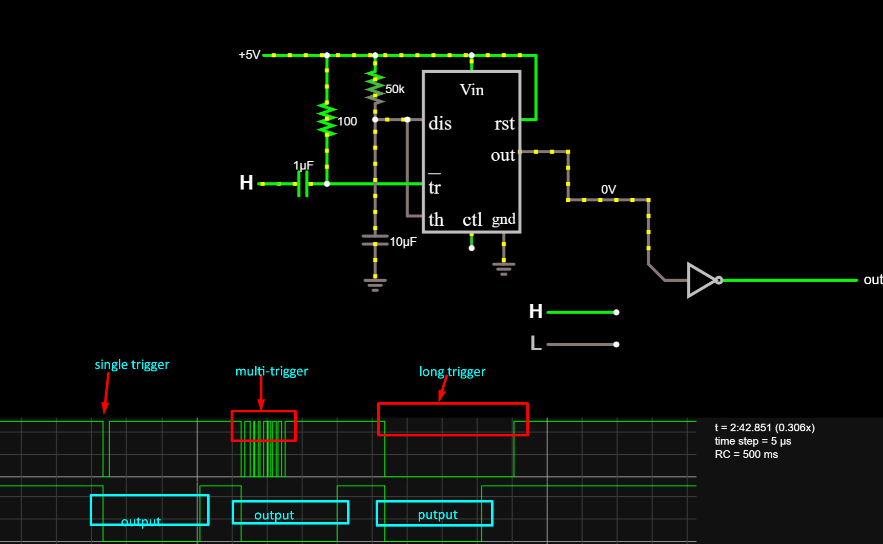
enter image description here

\$\endgroup\$

1 Answer 1

2
\$\begingroup\$

First: The simulation is only as good as the simulator software model of the NE555.

Second: The feature you are discussing is called "retriggering". Specifically, you are asking for a non-retriggerable timer. That is, a trigger that does not repond to a second trigger. This non-retriggerable feature is the default of a real 555 timer.

However, the 555 output will stay high as long as the trigger is held "low". So, you have perfectly addressed that with your trigger capacitively coupled to your switch and designed with an RC time constant much shorter than your output.

Summary, I believe your simulation tool's model of the 555 timer is not accounting for some of the finer details of the 555 chip design regarding retriggering and long triggers.

It may be easiest to create a circuit on a breadboard with a 2-second delay and test it in real life.

\$\endgroup\$
3
  • \$\begingroup\$ Thank you for the insight. If I want to implement a non-retriggerable timer, how do I approach it? \$\endgroup\$
    – Adnan
    Commented Oct 28, 2021 at 5:01
  • \$\begingroup\$ Your 555 chip (and circuit) should be non-retriggerable as you've designed it. I believe your simulator does not define the behavior of a real 555 timer correctly. You should try your circuit with a real chip on a real breadboard. I think it will give you want you want. You can also try a different simulator like LTSpice. \$\endgroup\$ Commented Oct 28, 2021 at 6:06
  • \$\begingroup\$ Or you can try a CD4047 logic chip that has a better-defined setup for triggerable/non-retriggerable, mono-stable/astable by setting certain pins high or low. Exact instructions at top of page 2 of datasheet. ti.com/lit/ds/symlink/… this will work if you don't need more than 1 or 2 mA of output drive. The 555 timer can drive loads up to 200mA. \$\endgroup\$ Commented Oct 28, 2021 at 6:08

Your Answer

By clicking “Post Your Answer”, you agree to our terms of service and acknowledge you have read our privacy policy.

Not the answer you're looking for? Browse other questions tagged or ask your own question.