0
\$\begingroup\$

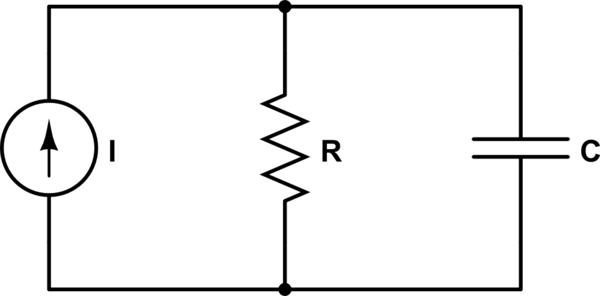
I want to model an Avalanche Photodiode (APD) in LTSpice. Is the below an appropriate representation?:

Assumed AOD Representation

simulate this circuit – Schematic created using CircuitLab

If so, why is the diode resistance in parallel with the current source? My intuition tells me it should be in series since the current passing through the diode would feel a resistance.

Also, in this configuration, the APD is not biased, but if it was then the current would vary with the applied bias. Since the current changes according to the voltage, that gives me more reason to believe that the resistance should be in series with the current source.

\$\endgroup\$
4
  • 2
    \$\begingroup\$ A resistor in series with a current source does nothing - a current source has infinite resistance already. Parallel is correct. \$\endgroup\$ Commented Jan 15, 2022 at 1:05
  • \$\begingroup\$ You can frequently ignore the resistance since it will be very large and almost no current will pass through the resistor. \$\endgroup\$ Commented Jan 15, 2022 at 2:14
  • \$\begingroup\$ The leakage current is modelled by the high resistance across a negative bias current source. \$\endgroup\$
    – D.A.S.
    Commented Jan 15, 2022 at 3:05
  • \$\begingroup\$ Cole, Hamamatsu is a reasonable place to go for a good overview. For PDs, you might read this for modeling. But for APDs, perhaps here. However, I'm pretty sure you aren't ready. You wrote, "My intuition tells me it should be in series since the current passing through the diode would feel a resistance." That sentence alone tells me that you have some study ahead before those two documents can trickle in well. \$\endgroup\$
    – jonk
    Commented Jan 15, 2022 at 7:31

1 Answer 1

4
\$\begingroup\$

If so, why is the diode resistance in parallel with the current source? My intuition tells me it should be in series

A resistor in series with an ideal current source still produces exactly the same current through its load regardless of the voltage across the terminals. So its behavior is exactly the same as the ideal current source with no resistor.

Since the current changes according to the voltage, that gives me more reason to believe that the resistance should be in series with the current source.

On the contrary, the resistor must be placed in parallel with the current source in order to have the affect of producing less output current for high voltage loads and vice versa.

the APD is not biased, but if it was then the current would vary with the applied bias.

For the record, the effect of bias on the APD current is highly nonlinear, and can't be modelled by adding a simple resistor to the model. A simple(ish) model of an APD might look like this:
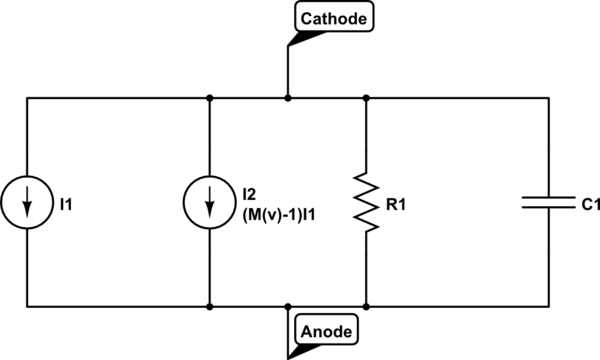
schematic

simulate this circuit – Schematic created using CircuitLab

The function \$M(v)\$ gives the avalanche gain of the device. It is (as mentioned before) a highly nonlinear function, something like an exponential of an exponential function of the voltage across the device terminals.
\$\endgroup\$
0

Your Answer

By clicking “Post Your Answer”, you agree to our terms of service and acknowledge you have read our privacy policy.

Not the answer you're looking for? Browse other questions tagged or ask your own question.