I've been playing around with an MPU6050 (GY-521 board) with a Nucleo L476RG.
I think I'm reading the gyroscope correctly, but it seems like the values are only changing when the sensor is moving, and when it stops, the orientation goes back to 0, 0, 0.
Is this normal? I though the sensor would keep track of the orientation with respect to its initial reference frame. This is how I'm initializing and reading the sensor data:
void mpu6050::init(I2C_HandleTypeDef& hi2c) {
  uint8_t check, data = 0;
  HAL_I2C_Mem_Read(&hi2c, MPU6050_ADDR, WHO_AM_I_REG, 1, &check, 1, 1000);

  // If the device is present
  if (check == 104) {
    // Write 0x0 to power management register to wake up the sensor
    HAL_I2C_Mem_Write(&hi2c, MPU6050_ADDR, PWR_MGMT_1_REG, 1, &data, 1, 1000);
    HAL_Delay(100);

    // Disable FSYNC and set accelerometer and gyro bandwidth to 44 and 42 Hz, respectively
    // data = 0x03;

    // HAL_I2C_Mem_Write(&hi2c, MPU6050_ADDR, CONFIG_REG, 1, &data, 1, 1000);

    // Set data output rate for 1khz, formula is: sample rate = gyro output rate / (1 + reg val)
    data = 0x07;
    HAL_I2C_Mem_Write(&hi2c, MPU6050_ADDR, SMPLRT_DIV_REG, 1, &data, 1, 1000);

    // Set gyroscope full scale range
    // Range selects FS_SEL and AFS_SEL are 0 - 3, so 2-bit values are left-shifted into positions 4:3
    HAL_I2C_Mem_Read(&hi2c, MPU6050_ADDR, GYRO_CONFIG_REG, 1, &check, 1, 1000);
    uint8_t config = check & ~0xE0;
    HAL_I2C_Mem_Write(&hi2c, MPU6050_ADDR, GYRO_CONFIG_REG, 1, &config, 1, 1000); // Clear self-test bits [7:5]
    config = check & ~0x18;

    HAL_I2C_Mem_Write(&hi2c, MPU6050_ADDR, GYRO_CONFIG_REG, 1, &config, 1, 1000); // Clear AFS bits [4:3]
    data = 0x0;

    HAL_I2C_Mem_Write(&hi2c, MPU6050_ADDR, GYRO_CONFIG_REG, 1, &data, 1, 1000);

    // Set accelerometer configuration
    HAL_I2C_Mem_Read(&hi2c, MPU6050_ADDR, ACCEL_CONFIG_REG, 1, &check, 1, 1000);
    config = check & ~0xE0;

    HAL_I2C_Mem_Write(&hi2c, MPU6050_ADDR, ACCEL_CONFIG_REG, 1, &config, 1, 1000); // Clear self-test bits [7:5]
    config = check & ~0x18;

    HAL_I2C_Mem_Write(&hi2c, MPU6050_ADDR, ACCEL_CONFIG_REG, 1, &config, 1, 1000); // Clear AFS bits [4:3]
    data = 0x0;

    HAL_I2C_Mem_Write(&hi2c, MPU6050_ADDR, ACCEL_CONFIG_REG, 1, &data, 1, 1000);
  }
}

// Read accelerometer registers
// Each axis for accel readings is split between high and low registers
// There's a total of 6 bytes of data (1 for each register) to read
void mpu6050::read_accel(I2C_HandleTypeDef& hi2c, float& Ax, float& Ay, float& Az) {
  uint8_t accel_data[6];

  // Get High register reading, shift 8 bits and OR with low register reading
  HAL_I2C_Mem_Read(&hi2c, MPU6050_ADDR, ACCEL_XOUT_H_REG, 1, accel_data, 6, 1000);
  HAL_Delay(100);

  int16_t accel_X_raw = (int16_t)((accel_data[0] << 8) | accel_data[1]);
  int16_t accel_Y_raw = (int16_t)((accel_data[2] << 8) | accel_data[3]);
  int16_t accel_Z_raw = (int16_t)((accel_data[4] << 8) | accel_data[5]);

  // convert raw values to g's
  Ax = accel_X_raw / 16384.0;
  Ay = accel_Y_raw / 16384.0;
  Az = accel_Z_raw / 16384.0;
}

// Read gyroscope registers
// Each axis for gyro readings is split between high and low registers
// There's a total of 6 bytes of data (1 for each register) to read
void mpu6050::read_gyro(I2C_HandleTypeDef& hi2c, float& Gx, float& Gy, float& Gz) {
  uint8_t gyro_data[6];

  // Get High register reading, shift 8 bits and OR with low reading
  HAL_I2C_Mem_Read(&hi2c, MPU6050_ADDR, GYRO_XOUT_H_REG, 1, gyro_data, 6, 1000);
  HAL_Delay(100);

  int16_t gyro_X_raw = (int16_t)((gyro_data[0] << 8) | gyro_data[1]);
  int16_t gyro_Y_raw = (int16_t)((gyro_data[2] << 8) | gyro_data[3]);
  int16_t gyro_Z_raw = (int16_t)((gyro_data[4] << 8) | gyro_data[5]);

  // convert raw values to deg/s
  Gx = gyro_X_raw / 131.0;
  Gy = gyro_Y_raw / 131.0;
  Gz = gyro_Z_raw / 131.0;
}
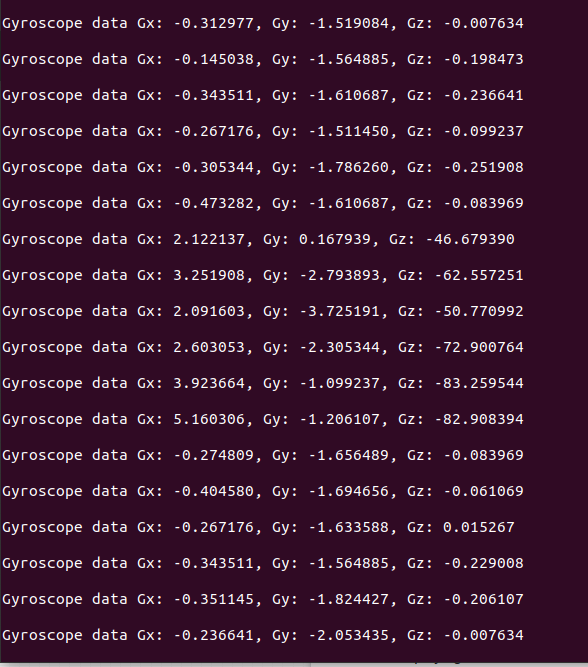
With the sensor on a bread board on my table, if I rotate it 90° clockwise only and then leave it, this is what the output looks like:
Should the Gz value not stay at -90°?

