I am using this BLDC motor [https://uav-en.tmotor.com/html/2018/navigato_0402/52.html] as a generator. The device providing the mechanical drive turns the motor about half a turn and not at a linear speed, thus my output is not a perfect sine wave. I am using 0.3R resistors as a load in a star configuration, and I believe, but not certain, that the motor is wired in a star too, so I think this is my schematic. Note, the motor just has 3 wires, no neutral and I checked for continuity with the motor case, in case that is the neutral.
EDIT 8th Apr - the schematic below is incorrect, I have just got a reply from the supplier of the motor, it is actually in a Delta configuration.
Before I get into the actual output, can I just confirm a few things first. I have searched online for how to calculate 3 phase power (assuming a normal case of a perfect sine wave) and got this in a few places:
P = √3 × pf × I × V
However, I'm unsure if the voltage above is line to line, or line to neutral, which I don't have anyway. I am measuring the voltage across one of my three load resistors, so that's line to line, yes?
As I don't know my current, but know my load, can I rewrite this as such:
P = √3 × pf × (V^2 / R)
I am assuming that the voltage should be RMS, and that my load, being resistors, have a pf of 1.
Next is the issue of taking my imperfect sine wave output and trying to get an average power figure. So I need to get an RMS value. I did the following [https://www.techwalla.com/articles/how-to-get-the-rms-in-excel]:
Export the data from my 'scope and ran ABS on it, converting negative values to positive. Then squared each data point value, then averaged these values, and took the square root of the average.
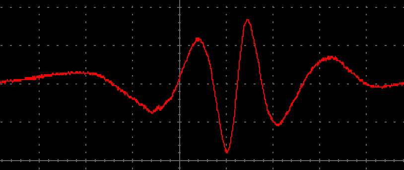
This is the output of my motor/generator (just showing one phase here):
So using my rewriten 3 phase formula, and my RMS method, am I getting the correct average power output?


