1
\$\begingroup\$

I am looking at options for receiving the 50Hz (UK) mains hum from a nearby substation. The goal is to filter some measurements, so I need to produce pulses in time with the zero crossing (or peak). The substation will be around 40m away. The device can't simply be plugged into the mains unfortunately.

That means receiving the mains hum via an antenna, in the Super Low Frequency (SLF) band. What little information I could find suggests that the antenna needs to be fairly large (wavelength is just under 6,000,000m) with an amplifier and band-pass filter. There seems to be very little in the way of published schematics and antenna designs for this.

Are there any published designs for SLF receivers, or any good resources for building one?

\$\endgroup\$
4
  • 2
    \$\begingroup\$ Usually people are trying to get rid of the 50 or 60 Hz signal from their designs. For your case, an antenna at 1/2 lambda or full lambda is not at all feasible. Your best bet is to approach the design from a compromised antenna, with extreme directionality. This will be challenging though, because if a house or other power line is in your line of sight you will pick that up before pickup up the substation. Also, most subs are 3 phase, so you have to deal with receiving all 3 phases as well. The zero phase crossing for A, B and C phase are all going to be different. \$\endgroup\$ Commented Apr 19, 2022 at 14:47
  • 2
    \$\begingroup\$ At that frequency you'd best pick up the near field magnetic signal. Use the largest loop of wire you can get, or use a ferrite rod wound with many turns of wire for something more compact. There are some exquisitely sensitive magnetic detectors, which are probably out of most people's league (SquiDs and the llike). \$\endgroup\$
    – Neil_UK
    Commented Apr 19, 2022 at 15:24
  • \$\begingroup\$ Thanks. Yes, 3 phase is probably a going to make this one impossible. As you say @user3425949, most of the effort goes into eliminating mains hum so there isn't much out there on this topic. \$\endgroup\$
    – user
    Commented Apr 20, 2022 at 8:56
  • \$\begingroup\$ Meanwhile, too many of my designs start out as 50/60Hz detectors...accidentally. \$\endgroup\$ Commented May 3, 2022 at 21:36

2 Answers 2

2
\$\begingroup\$

If you are 40 meters away from a signal with a wavelength of 6000 km, you are definitely within the near field of the radiator. This means that the electric and magnetic fields can be (and will be) vastly different. The magnetic field will reflect the current in the wires, and the electric field, the voltage. Both of them will be problematic for detecting zero crossings.

The magnetic field is problematic for detecting zero crossings because in an electric power system, current and voltage do not need to be in phase, and commonly are not. Furthermore, current does not need to be sinusoidal, even when voltage is sinusoidal. If, however, you wish to monitor the magnetic field for some reason or another, a coil of wire will serve that purpose.

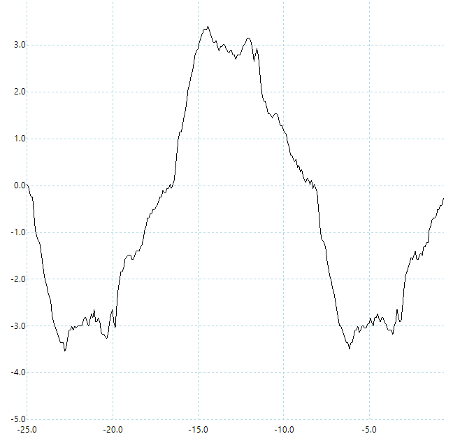
The electric field will be problematic for detecting zero crossings because of the means you will require to pick up the electric field. To pick up electric field, you should use two large conductive plates. The ground could theoretically be used for one of the plates, but I would be wary of what might be happening to fields in the ground, so let's assume two metal plates. The plates could theoretically be aluminum foil, but any movement in the plates will introduce noise into your system. So, the aluminum foil would need to be supported somehow to make the plates stiff. Perhaps a thin sheet of wood would work. So, your receiver will in essence work on the capacitance between your plates and the voltage source. Alas, a capacitor and the impedance of the voltage source together form a high pass filter. Even slight deviations from a sinusoid in the source will be "magnified" in your received signal. The following oscillograph shows the results of an experiment I did picking up the electric field from a extension cord (with no load) fed by an apparently clean sinusoidal mains voltage.
enter image description here

As you can see, it is pretty noisy. You could compensate by adding a low pass filter. This would remove some of the high frequency components of the signal. However, a problem will still remain. The intrinsic high pass filter, and the additional low pass filter will almost certainly introduce phase shift in your signal. How you will ensure the net phase shift is negligible is a problem that you will need to resolve if you wish to recover the zero crossing points of the signal.

\$\endgroup\$
1
  • \$\begingroup\$ What about Hall effect sensors, would that be another option instead of coils? \$\endgroup\$
    – Lundin
    Commented Apr 21, 2022 at 6:28
0
\$\begingroup\$

In addition to my comment I made yesterday, there is also a story I recall watching (after a search, I can't find the resource) that used the 50/60 Hz cycle that was recorded by a cellphone as forensic evidence. The audio contained the "hum," which has variations in the phase. That phase information was compared to the power company records to timestamp an audio recording. Again, it is likely the hum that was picked up was only a single phase though.

\$\endgroup\$

Your Answer

By clicking “Post Your Answer”, you agree to our terms of service and acknowledge you have read our privacy policy.

Not the answer you're looking for? Browse other questions tagged or ask your own question.