0
\$\begingroup\$

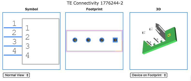
I want to use this terminal block on my PCB. However, the schematic and PCB footprint Mouser provides are unclear to me. Why are there 4 pins and what is my signal and ground pin? The data sheet does not provide any detail either.

EDIT: To provide more context about what I am looking at; this is the footprint Mouser provides:

enter image description here

\$\endgroup\$
2
  • \$\begingroup\$ Distributor-provided footprints, and ones found at UltraLibrarian or SnapEDA or wherever, are convenient when they're correct... but they can be flawed. Out of perhaps a hundred footprints I've downloaded via these resources, I've had about four or five that were wrong. Manufacturer drawings and footprints, when available, are generally more reliable. \$\endgroup\$
    – JYelton
    Commented Aug 12, 2022 at 21:50
  • \$\begingroup\$ Those footprints are probably generic, and intended as samples to cover the whole terminal block family. You should learn to create your own footprints, rather than rely on footprints from random uknown sources. \$\endgroup\$ Commented Aug 12, 2022 at 22:16

2 Answers 2

1
\$\begingroup\$

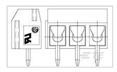
There aren't four pins. You're seeing an image of the series of connectors which shows a three-pin version on the right and a side-view on the left:
Product image

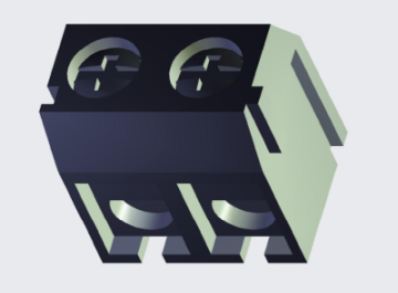
The connector you order will only have two positions based on the part number 1776244-2. If you click "3D Customer View Model" you can see that the actual part just has two positions as per the description:
3D Customer View

Ground and signal are whatever pins you decide. The connector is completely ambivalent about what you assign.

One final note, I think you mean "datasheet" when you say "schematic." In this context, "schematic" would mean an electrical circuit diagram showing how components are interconnected. If you were following a schematic for an existing product or design, then assignment of signal and ground to connector pins would be important.

\$\endgroup\$
3
  • \$\begingroup\$ Please see the edit I made. I think it will provide clarity as to what I am referring to \$\endgroup\$
    – ALUW
    Commented Aug 12, 2022 at 21:29
  • \$\begingroup\$ The drawings appear to be generic (a polite term for incorrect) that is not specific to the 2 position connector. The 3D model correctly shows the 2 pin connector. Which pin you use for signal and which for ground is your choice. \$\endgroup\$
    – Ian Bland
    Commented Aug 12, 2022 at 21:47
  • \$\begingroup\$ @ALUW Unfortunately I think the footprint that Mouser's linking to or providing is incorrect. Be sure to let them know. I have had reasonably fast response to incorrect footprints by distributors such as Mouser and Digikey. \$\endgroup\$
    – JYelton
    Commented Aug 12, 2022 at 21:51
1
\$\begingroup\$

Mouser is offering you an incorrect footprint. You'll need to remove the extra pins yourself. Make sure the print is otherwise correct.

It is a two pin device, there should not be 4 holes in the PCB or 4 pins on the schematic symbol.

\$\endgroup\$

Your Answer

By clicking “Post Your Answer”, you agree to our terms of service and acknowledge you have read our privacy policy.

Not the answer you're looking for? Browse other questions tagged or ask your own question.