1
\$\begingroup\$

I understand why capacitive reactance reduces inductive reactance mathematically, having a result of zero at resonant frequency.

enter image description here

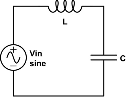
But how to physically explain the flow of electrons in series LC circuit, where the coil lags the flow of current (electrons) relative to the applied voltage? How can the capacitor counteract this? By reducing the coil's back EMF? I assume, that if coil blocks electrons flow (current), capacitor can`t counteract it, especially when there is no voltage on its terminals. As the voltage of the power source increases, the first thing it encounters is a coil that prevents it from flowing current. How can the capacitor counteract this, if from the point of view of the power source it is a short circuit at the very beginning (no voltage across capacitor's terminals)? How it can cancel phase shift created by coil?

\$\endgroup\$
8
  • 2
    \$\begingroup\$ Please don't confuse this by talking about a flow of electrons. For this sort of analysis we use conventional current. Do you understand the basic capacitor and inductor formulas? Additionally, capacitive reactance does not change inductive reactance one bit. \$\endgroup\$
    – Andy aka
    Commented Dec 2, 2022 at 11:01
  • \$\begingroup\$ Yes, I think so. I read a lot about this topic. I know, that capacitor's reactance is opposite to coil's reactance and the sum (at resonance frequency) is zero, etc. But how we can visualize it? \$\endgroup\$
    – Szymon
    Commented Dec 2, 2022 at 11:07
  • \$\begingroup\$ You said this in your question: I understand why capacitive reactance reduces inductive reactance mathematically <-- this is wholly untrue \$\endgroup\$
    – Andy aka
    Commented Dec 2, 2022 at 11:08
  • \$\begingroup\$ So, why the equation is X = XL - XC (in series, when we consider vectors)? I am newbie, so for me more important is intuition understanding, then equations. Sorry if my question has any logical mistakes. I can't sleep because of this topic :) \$\endgroup\$
    – Szymon
    Commented Dec 2, 2022 at 11:18
  • \$\begingroup\$ How is XC altering XL? \$\endgroup\$
    – Andy aka
    Commented Dec 2, 2022 at 11:26

1 Answer 1

1
\$\begingroup\$

For a start, forget about electrons. They have nothing to add to understanding here.

Secondly, you've drawn a zero impedance voltage source driving what will at resonance be a zero impedance load, so you won't be able to reason easily from cycle to cycle.

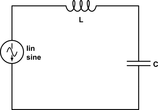
It may help to do a slight re-drawing of your diagram like this ...

schematic

simulate this circuit – Schematic created using CircuitLab

You now have something that does have a steady state.

Taking the flow of AC current from the current source as the reference, consider the voltage across the inductor, and the capacitor. One will lead it by 90 degrees, the other will lag it, so the two voltages will have a total phase difference of 180 degrees, they will be in antiphase.

At resonant frequency, the magnitude of these two voltages will be equal, and the voltage across the current source will therefore be zero.

Off resonance, the two voltages will not cancel, so there will be a residual voltage across the current source. This voltage will be less than that across either component, so the current source will 'see' a lower impedance than either the L or the C.

\$\endgroup\$

Your Answer

By clicking “Post Your Answer”, you agree to our terms of service and acknowledge you have read our privacy policy.

Not the answer you're looking for? Browse other questions tagged or ask your own question.