There are many peculiarities of switching converter supply design which can only be known after quite a bit of study and experience, and even then things have to be tried, tested and measured to make sure you got them right.
It seems to me that you don't know much about switching regulators and how they work, which is dangerous considering you want to do a mains voltage converter. You have to be sure you know the dangers and to stay safe: using an isolating transformer or a regulated high voltage bench supply (also isolated from the mains), with a current limit (you could use a plain incandescent bulb in series to limit the current and damage during your tests.
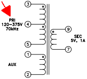
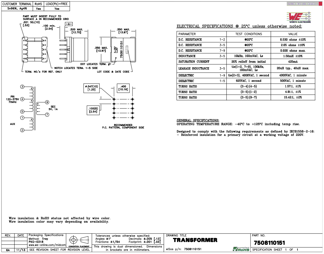
That being said, in your particular case, it seems that you didn't pay attention to the transformer details. If you look at the detail below, you will see the input voltage being specified as a range of voltages from 120V to 375V:

This, of course, refers to the rectified peak DC voltage, which means the input AC voltage can be anywhere from 85V to 265V.
The "nature" of switching converters or voltage regulators is that they can take a fairly wide range of input/primary voltages and still deliver a steady output voltage through the "magic" of PWM or Pulse Width Modulation: in your case, when the input voltage is at the specified minimum of 120VDCpeak, the pulse width will be at its maximum (we will assume a constant output load to simplify explanation here).
If your input voltage goes to 240VDCpeak, the pulse width will be half as much as it was at 120VDC, similar thing will happen throughout the input voltage range where pulse width will be adjusted by the same ratio (as the input voltage change) and that will be regulated by the switching IC.
Now, to your questions.
First of all, this IC doesn't need auxiliary winding as it has this mentioned right on the first page of its datasheet:
• Dynamic Self−Supply: No Need for an Auxiliary Winding
If you are not going to use the auxiliary winding on this transformer, I would strongly suggest loading it with a relatively large value resistor to keep it from reaching very high voltages, due to leakage inductance and capacitance, and breaking down the insulation. At 170V input, and the ratio of 3-5 connections to 1-2 is 4.91 or about 5:1, that means roughly about 170:5 or 34V on average. I am not very skilled with switchers, but I think that you can go with about 33kΩ, 1/4W resistor, or use a range from 10kΩ to 100kΩ and up to 1W.
Better and simpler yet would be to get a transformer with the same ratios but without an auxiliary winding since you don't need it with this particular IC, but that would increase the power dissipation of the IC.
If you already have the IC and want to use the auxiliary winding to supply the IC, you would need to add an ultrafast diode and a capacitor at its output, plus a relatively large resistor in series to limit the current into the Vcc pin of the IC.
The datasheet specifies an absolute maximum internal consumption current (ICC1) of 1.3mA, plus an absolute maximum input current of 15mA when the internal "Active voltage clamp" (like a zener diode) is activated at 8.2V, BUT there is an OVP (Over-Voltage Protection) circuit which kicks in before that to stop oscillating at no less than 6mA of clamp current, which adds up to the ICC1 giving a maximum nominal operating current of 1.3+6=7.3mA
This gives Imin=1.3mA, Imax=7.3mA, Vcc=8V, and the Vaux would be going from 120-200VDCpeak divided by the ratio of 4.91 = 24-40VDCpeak(it's actually 40.7, but can be rounded to 40V due to the rectifying diode and other losses). I have used 200V as a maximum to cover for an increased line voltage, just in case. Additionally, we need to account for about 40% auxiliary voltage drop when the 5V output is not loaded. This means we're left with 14.4-24V as our minimum Vaux (I will round 14.4 down to 14).
The current-limiting resistor (Rlimit) needs to keep the current through it below 7.3mA, but above 1.3mA to make sure the IC will neither overheat nor go into the Dynamic Self-Supply mode (DSS mode), which would increase power dissipation of the IC.
First we figure out the minimum and maximum voltages across the resistor:
VRmin=14-8=6V; VRmax=24-8=16V
Then we only need to calculate the maximum resistance which gives more than the minimum required current at the minimum auxiliary peak voltage:
Rmax=6V/1.3mA=4.6kΩ or 3.9-4.3kΩ in standard values
If you also want this resistor to determine the OVP (Over-Voltage Protection) point at your 5V output, you need to calculate it to include the 6mA IOVP, so that the IC stops supplying the output once the 5V output goes above a certain limit.
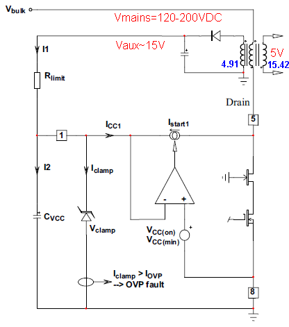
For that, you use the nominal Vaux which is related to the 5V output by the windings ratio which is:
AUXratio/SECratio=15.42/4.91=3.14 Vaux to Vsec ratio, or 3.14x5=15.7Vaux
To help visualize this part of the equation, here is a simple schematic:

For the OVP to be activated, the current going through the Rlimit has to be at least 6mA, but can be as high as 11mA (IOVP in datasheet) - the exact value is determined experimentally.
If we decide that the OVP should be activated at 6V on the 5V output, the Vaux will then be about 3 times higher than the output, i.e. 18V.
Now we calculate the Rlimit: Vaux(18V)-Vclamp(8V) / I1(6mA) = 10/0.006 = 1.67kΩ. Since the required tripping current for OVP can be as high as 11mA or almost double (each IC is unique in this respect), this resistor may need to be adjusted to below 1kΩ.
But you may simply assume Vaux-Vclamp / 6mA, or 16V-8V / 6mA; 8/0.006=1.33kΩ, and then go to 1.5kΩ to make sure OVP doesn't interfere with normal operation.
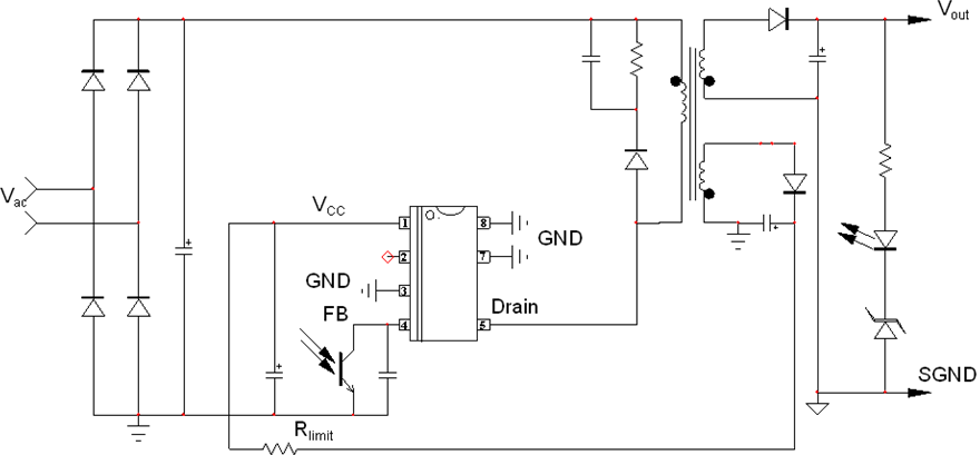
Finally, here is a typical application example with this IC:

I hope that you know how to set up an opto-coupler with a zener or a TL431 IC to control the output voltage, how to follow the polarity dots on the transformer, and how to calculate the RCD combination for reducing spikes across the primary transistor.
All of this should help you get started.
It should also help you realize how difficult and complex it is to design and make a switching power supply, and I have only shown you a part of it.
If you have any questions, feel free to ask below.


