Background
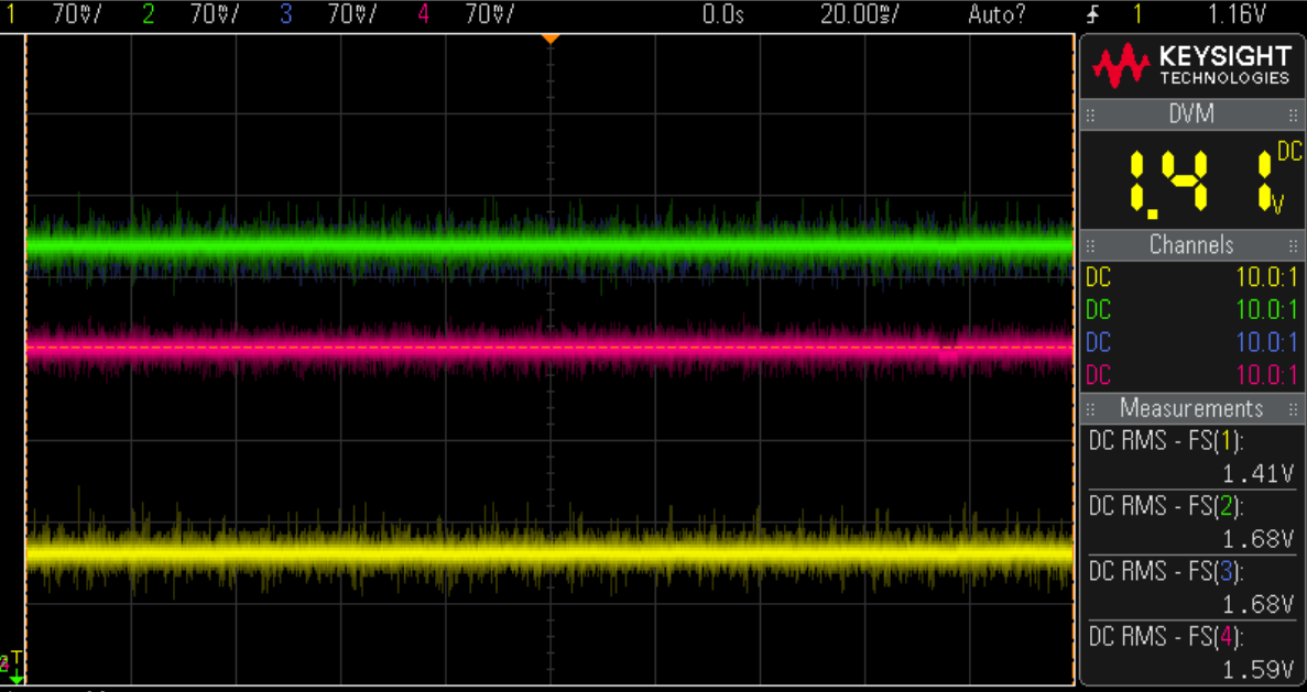
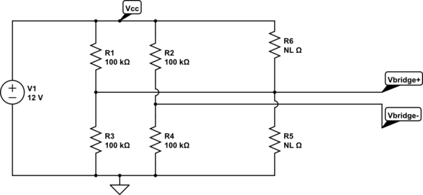
I have a sensitive magnetic sensor that is packaged as a wheatstone bridge with a 20k device resistance. I am using it to measure the rotation of a magnet. It is possible to calibrate out the offset voltage by applying a voltage to Vref of the instrumentation amplifier when the offset is constant (like with a with a strain gauge). However, the offset of the magnetic sensor can vary depending on the orientation in the earths magnetic field. Here is an example with two sensors.
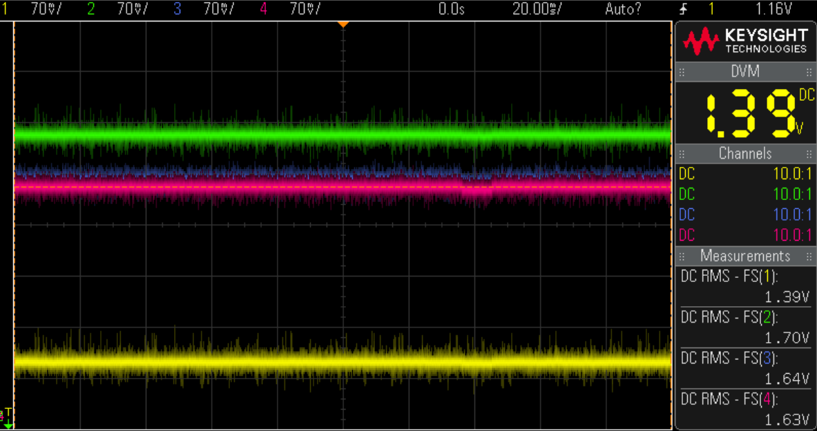
Green & Yellow = Sensor 1
Pink & Blue = Sensor 2
Here are the same two devices rotated by 90 degrees. The DC offset changes from 20-40mV. Also note sensor 1 has a difference of 27mV between differential pairs and sensor two has a difference of 9mv.
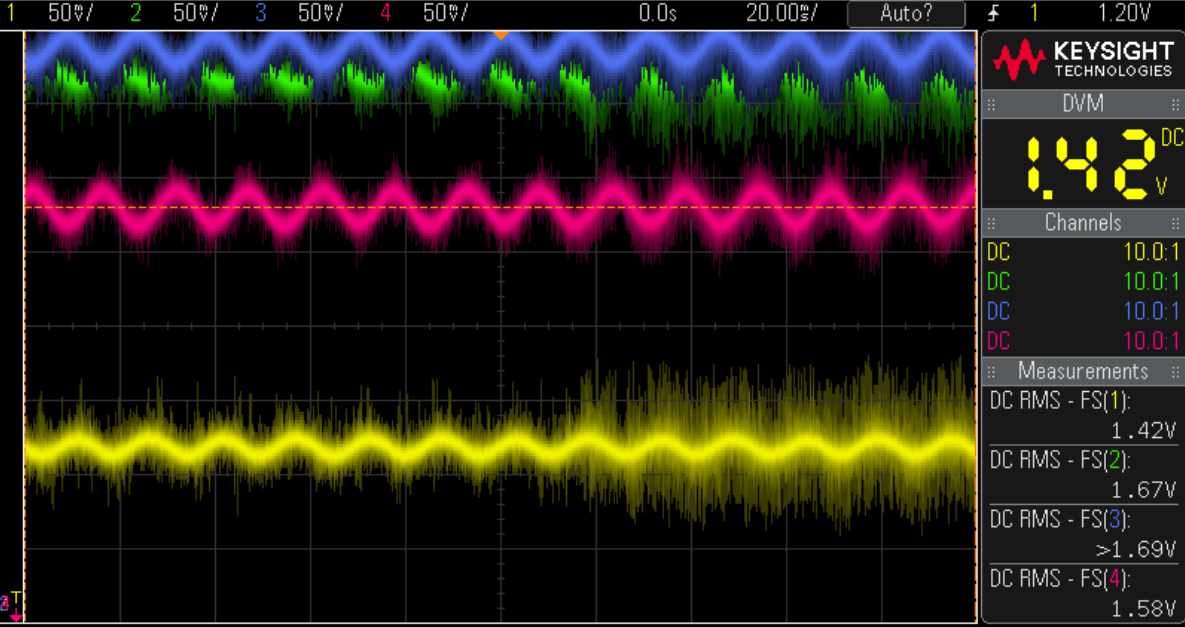
Here is a screenshot of the magnet rotating which produces a ~50mV sine wave
Problem
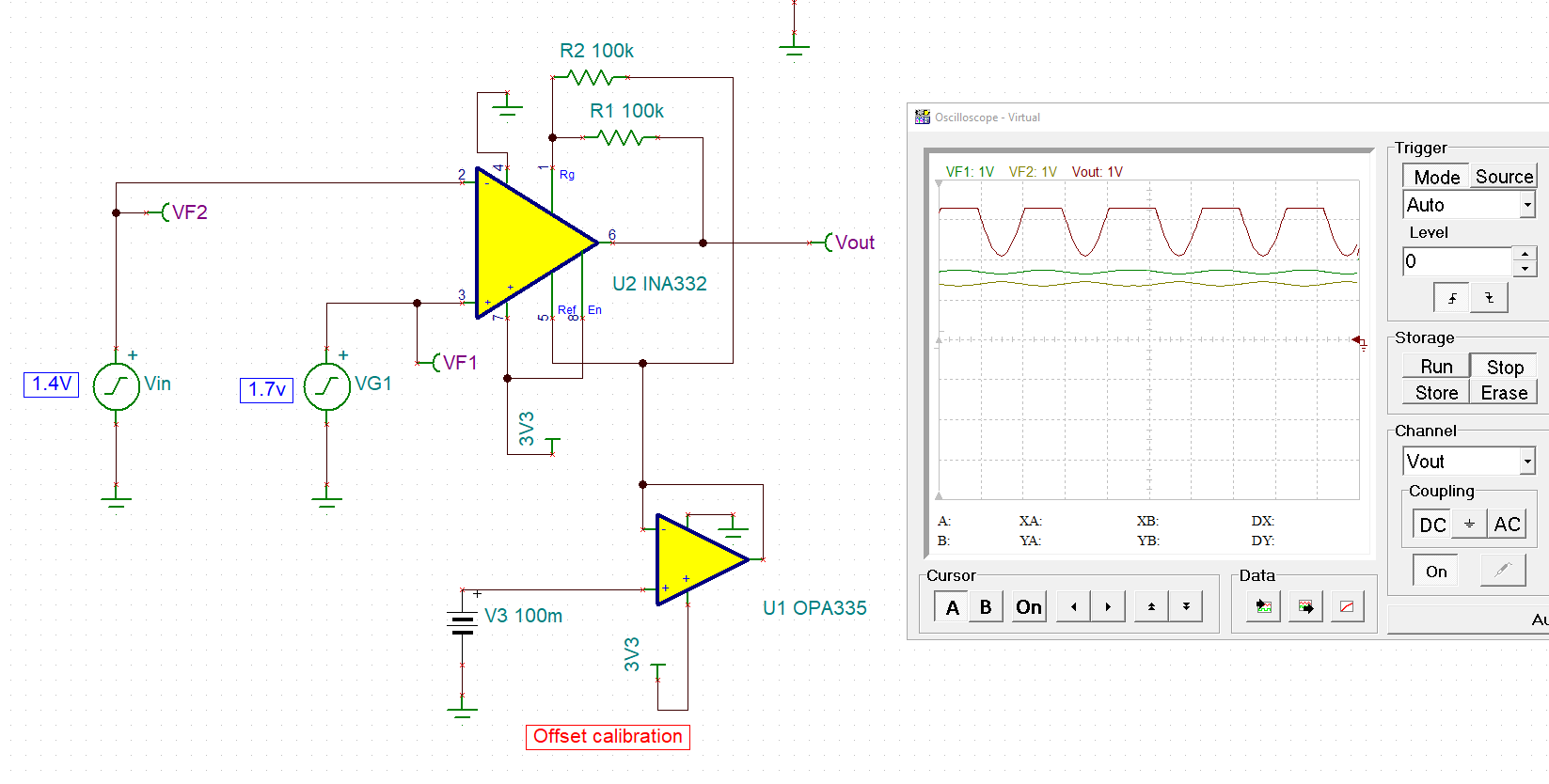
I have built a circuit using the INA321, but when the offset gets too large the opamp rails and produces clipped output. Even when the output is not clipped, the large DC offset change in the output makes it hard to count zero crossings which is my end goal.
Question
How can I compensate for the offset variance due to device differences and the earths magnetic field?
Using a high pass filter is not an option because I need to be able to measure very slow frequency. My power budget is also very limited so this needs to be done without the use of a microcontroller.

