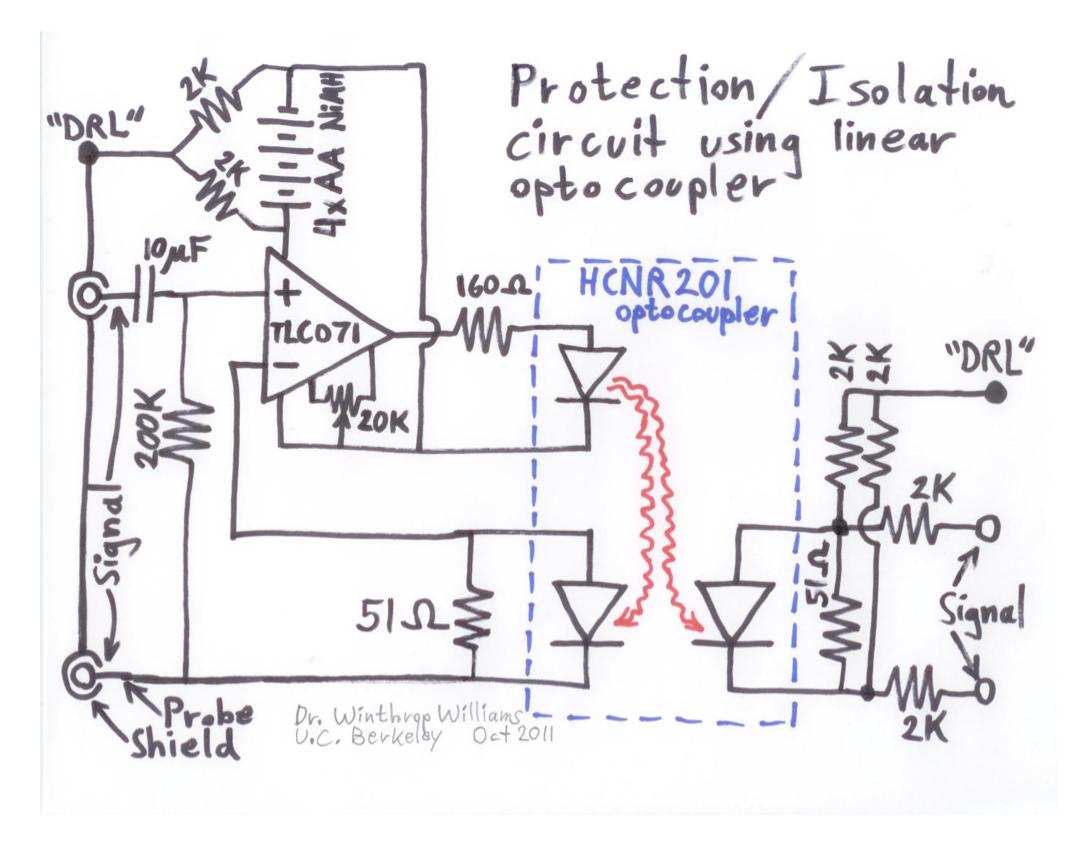
I'm trying to understand the following circuit, which I found in this document (on page 5). The purpose of the circuit is to go between a set of EEG electrodes and an EEG signal amplifier, and protect the EEG user from any accidental electrical discharge from the EEG amplifier.
I've already analyzed the circuit and I think I have most of it figured out. It looks like the left side connects to the actual scalp electrodes, and the right side feeds into the amplifier circuit. The 4xAA batteries creates a +6V voltage rail, so the DRL on the left is driven to +3V. The TLC071 is just a normal op-amp (powered by the batteries,) and there's an RC high-pass filter on the far left to eliminate any dc offset between electrode 1 and electrode 2. The op-amp and the optocoupler together form an isolation amplifier circuit that, in summary, sets the output differential signal (the difference between the two points on the right marked "signal") equal to the input differential signal (the difference between the two points on the left marked "signal.")
There are still 2 things I'm not sure about.
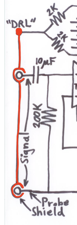
First, what do the "probe" and "shield" markers mean?
The "shield" seems to point to this strange structure that connects all 3 electrodes. I've highlighted this structure in red below. What exactly is it? I've never seen this in a circuit diagram before.
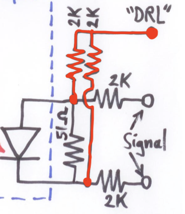
Second, what is the purpose of the section on the far right that connects to the "DRL" marker? Where is that rightmost "DRL" supposed to connect to? In the original document, the discussion of the actual amplifier circuit only mentions the two signal inputs, which makes me think that this rightmost DRL might be connected directly to the leftmost DRL, but I'm not sure if that's really the case. Below I've highlighted in red the part that I'm asking about.
One last thing: Is there any reason why the DRL pins are colored black and the signal pins are colored white, or is that just a stylistic choice?


