My oscilloscope has 100 MHz -3dB bandwidth. -3dB is 0.707 units (\$\sqrt{2} / 2\$). What does this mean, why 70.7% attenuation? Is there any particular reason for this attenuation level?
5 Answers
Voltage vs Power when using dB
The -3dB point is also known as the "half power" point. In voltage it may not make not make tons of sense as to why we use (\$\sqrt{2}/2\$), but lets look at an example of what it means in the sense of power.
First off, \$P=V^{2}/R\$, but lets assume R is a constant 1 \$\Omega\$. Because of the constant 1ohm, we can remove it from the equation all together.
Lets say you have a signal at 6 V, its power would then be \$(6 \text{ V})^2 = 36 \text{ W}\$.
Now I take the -3dB point, \$6\text{ V} \cdot \left( \frac{\sqrt{2}}{2} \right) = 4.2426\text{ V}\$.
Now lets get the power at the -3dB point, \$4.2426 \text{ V}^2=18 \text{ W}\$.
So originally we had 36 W, now we have 18 W (which of course is half of 36 W).
Application of -3dB in Filters
The -3dB point is very commonly used with filters of all types (low pass, band pass, high pass...). It is just saying the filter cuts off half of the power at that frequency. The rate at which it drops off depends on the order of the system you are using. Higher order can get closer and closer to a "brick wall" filter. Brick wall filter being one that just before the cutoff frequency you are at 0dB (no change to you signal) and just after you are at -∞ dB (no signal passes through).
Why filter the input to an Oscope?
Well, many reasons. All devices (analog or digital) have to do something with the signal. You can go as simple as a voltage follower up to something more complex like showing the signal on a screen or turning the signal into audio. All of the devices required to convert your signal into something that is usable have attributes about them that are frequency dependent. One simple example of this is an opamp and its GBWP.
So, on an O-scope they will add a low pass filter so that none of the internal devices are having to deal with frequencies above what they can handle. When an oscope says its -3dB point is 100 MHz they are saying they have placed a low pass filter on its input has a cut off frequency (-3dB point) of 100 MHz.
-
1\$\begingroup\$ I was half way through writing more or less the same. You beat be to it :-( \$\endgroup\$– uɐɪCommented Nov 19, 2010 at 14:11
-
1\$\begingroup\$ The oscope is going to have many things internal to it that will all be somewhat frequency dependent. When they rate the scope they are just saying that you will be able to get accurate readings within 3db up to that frequency. \$\endgroup\$– KellenjbCommented Nov 19, 2010 at 17:37
-
1\$\begingroup\$ @Kortuk: The issue isn't just aliasing. An AC signal of a given amplitude will change at a rate proportional to the frequency, and many circuits have parts which will not behave properly on signals which change too fast. If a device has a filter to attenuate higher frequencies at a rate of 6dB/octave (doubling the frequency halves the amplitude), then one can guarantee that if the input amplitude stays below a certain level, the rate of change on the output will stay below the device's limits. If one didn't include such an filter, the maximum distortion-free input level... \$\endgroup\$– supercatCommented Aug 9, 2012 at 17:34
-
3\$\begingroup\$ Strictly speaking half power is not -3dB but \$ 20 \cdot log \left( \dfrac{\sqrt{2}}{2}\right) \approx -3.0103 \text{ dB}\$ but it's close enough for most purposes. \$\endgroup\$ Commented Aug 28, 2014 at 17:27
-
4\$\begingroup\$ Chiming in 10 years later, but no one has pointed out that physically, the 3dB point exists as the point were the reactive contribution to impedence matches the resistive contribution in voltage divider (e.g. a filter). The impedence phasor on the complex plane has a magnitude of root(2) when the two are equal (and follows that half of that is Vout/Vin). Xc=1/(2pifc) and Zt = sqrt(R^2 + Xc^2), and .707... falls right out of that. \$\endgroup\$– FreemanCommented Dec 24, 2019 at 1:36
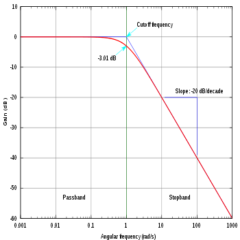
The modulus graphic on the bode diagram of a first order high pass or low pass filter, can be approximated by two lines. The point which the two lines meet, when compared to the real line gives us the number of -3db. This point is called the cutoff frequency.

So, lots of systems are designed to operate in normal conditions until they met the cutoff frequency when they lose at maximum 3db. If you operate with signal above that frequency the signal can be more attenuated.
More info in Wikipedia about continuous low pass filters.
The -3dB, come from 20 Log (0.707) or 10 Log (0.5). to determine the bandwidth of signal, when decrease the voltage from maximum to 0.707Max or decreasing the power from max to half power.
-
3\$\begingroup\$ This doesn't add anything to what the other answers already said. \$\endgroup\$ Commented Aug 28, 2014 at 16:50
-
2\$\begingroup\$ Short answer but helps. I got thrown off with the many tech terms on the accepted answer and why multiple 6V to sqr(2)/2 until I read this answer to relate "half power" to 0.5 instead then things started to make sense. \$\endgroup\$– KMCCommented Mar 12, 2020 at 12:50
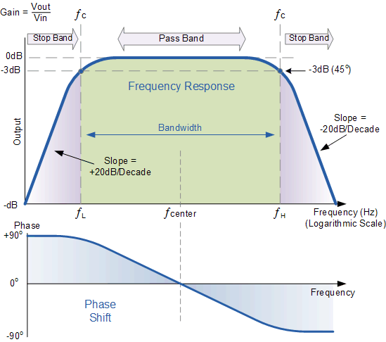
Kellenjb's answer is excellent, I just wanted to add a webpage that gave me a "Ohhh" moment when I was reading about this -3db thing. Maybe it helps to visualize.
I read a tutorial on Band Pass filters which includes a great image of a Bode Plot. You can see the key image below. It nicely illustrates how signal attenuation varies depending on the frequencies. We see there is no phase shift at the center frequency, so we have complete signal transmission. However as we go out of the Pass Band, we get to a point where the Band Pass Filter shifts the signal to lag or lead the central frequency by 45 degrees, and we see our point of -3dB.
At this point, we can note that sin(45°) = \$1/\sqrt(2)\$
For me the visual below really helps to bring some sense into this seemingly arbitrary choice of \$1/\sqrt(2)\$.
-
2\$\begingroup\$ Could you elaborate on what motivates the use of the sine function in establishing the phase shift of 45 degrees? The expression holds, obviously, but what suggests the use of the sine in the first place for the phase Bode plot? \$\endgroup\$ Commented Mar 4, 2017 at 16:33
The internal of the oscilloscope has an amplifier limitation. They called it dynamic range. If you use your scope pass the limitation, your reading will no longer be accurate. The linear amplifier will start to become nonlinear.
If you look at any block design of the oscilloscope, you will notice the input amplifier or preamplifier. You will not see filter block in front of it. The input signal is too small before it can be process by a filter. After you amplified the signal then you can use a filter. So the limitation is the preamplifier not a filter. When the o-scope give you a spec of 100 Mhz, 3dB. You can be sure it's referring to the preamplifier.
-
2\$\begingroup\$ Is there any particular value your answer adds to the question, that is not already amply covered by the existing answers? \$\endgroup\$ Commented Jan 18, 2014 at 10:18
-
\$\begingroup\$ Dynamic range has nothing to do with the question, which is about bandwidth. Ditto non-linearity, for the most part. Ditto preamplifiers. \$\endgroup\$ Commented Aug 28, 2014 at 21:37
-
\$\begingroup\$ The preamplifier is only one component of an oscilloscope. The 3db attenuation point does not refer to the preamplifier's limitation only, but the input system as a whole - which is not designed to exceed 100MHz. \$\endgroup\$– OsphoCommented Aug 28, 2014 at 23:38

