0
\$\begingroup\$

I am building a robotics control module which, of multiple parts, controls servos. When enough servos move, a large power drop causes the microcontroller to reset. This usually happens with 3/4 servos, although it doesn't always. I have tried to solve this by adding capacitors up to 1000 uF and 16 V at each section of the board, using linear regulators and buck converters to isolate the power, and increasing the battery voltage. Although improving, the problem still persists.

Here is the board specs: ESP32 Dev Kit C 2 DRV883 h-bridge drivers 4 MG90S servos 4 TT Motors

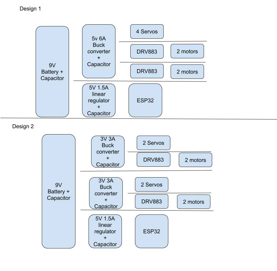
2 5v 3A Buck converters connected to 2 servos and 1 H-bridge or 1 5v 6A Buck Converterconnected to 4 servos and 2 H-bridges. 5v 1.5 A Linear regulator leading into the ESP32 Capacitors have been tested within each section of this circuit.

Power Layout, moves battery to part from left to right

How can I make sure that the ESP32 gets sufficient power when the servos move? Do 2 separate buck converters help isolate these power fluctuations compared to 1?

Thanks in advance.

\$\endgroup\$
1
  • \$\begingroup\$ You should get an oscilloscope trace of the input to the linear regulator under load and see how badly the battery voltage is dropping. \$\endgroup\$ Commented Apr 3 at 1:01

2 Answers 2

1
\$\begingroup\$

It's possible your battery is momentarily dipping below the ESP32 regulator's 'power ok' voltage (maybe 7V or so if it's an LM317 type.)

Try a regulator type that has a lower dropout.

The other possibility is that your battery is flaky (or not adequate?) and isn't holding up its voltage under load (you didn't mention its type.)

As far as the the two choices of configuration, the one with 3V regulators should have a worst-case lower peak draw since each supply is 9W (18W total) vs. 30W for the single 5V/6A unit.

That said, I still think your battery is not up to the task.

\$\endgroup\$
1
\$\begingroup\$

Try connecting a diode (e.g. 1N4001, or a Schottky diode) between the output of the 9V supply and the input of the 5V one. Then add a capacitor to the input of the 5V. This way, if a large load transient brings down the 9 V, the diode will isolate it and let the capacitor allow the 5V regulator to ride through it.

\$\endgroup\$

Your Answer

By clicking “Post Your Answer”, you agree to our terms of service and acknowledge you have read our privacy policy.

Not the answer you're looking for? Browse other questions tagged or ask your own question.