1
\$\begingroup\$

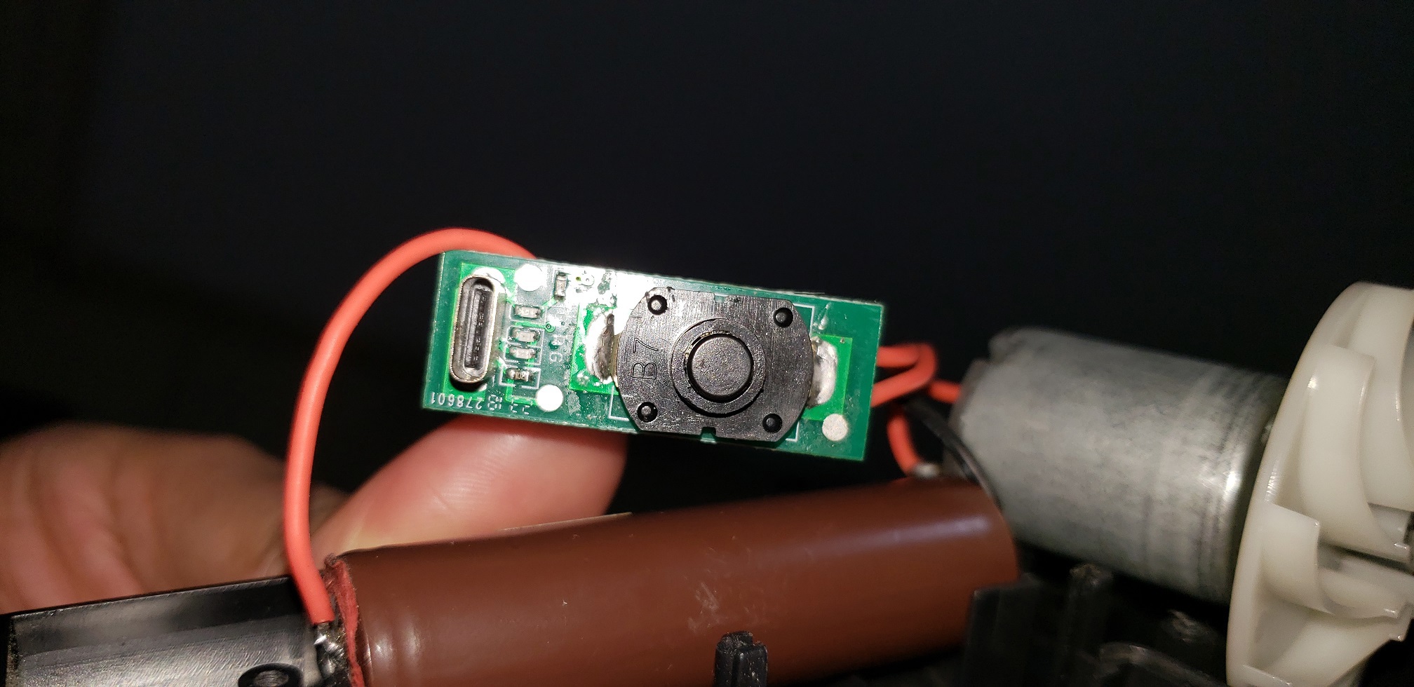
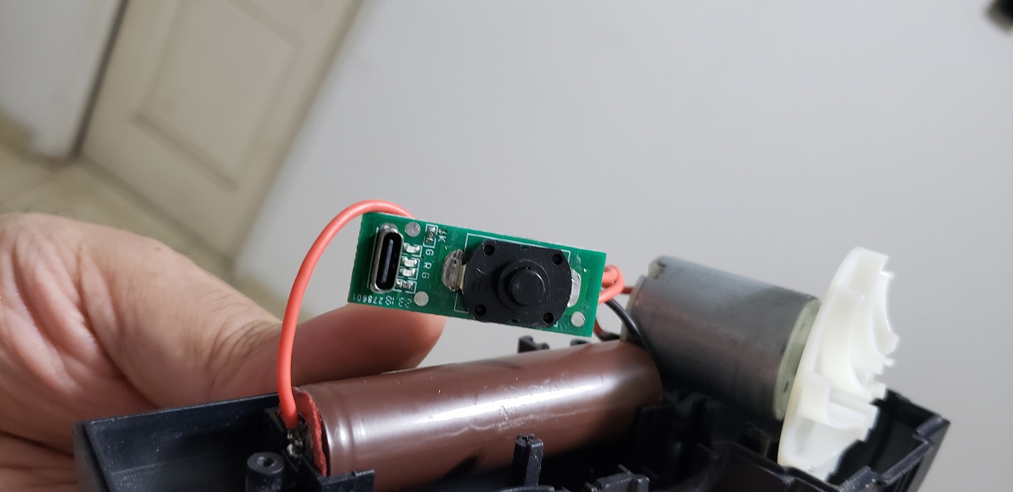
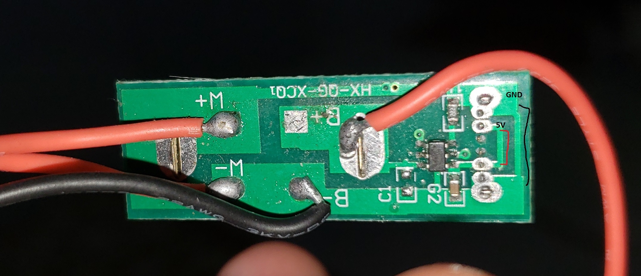
I have this USB-C rechargable vacuum cleaner. But 2 months after I replaced the battery for a bigger one (from 1500 to 3000 mah 18650) it is not charging anymore, it used to charge with the latter battery though.

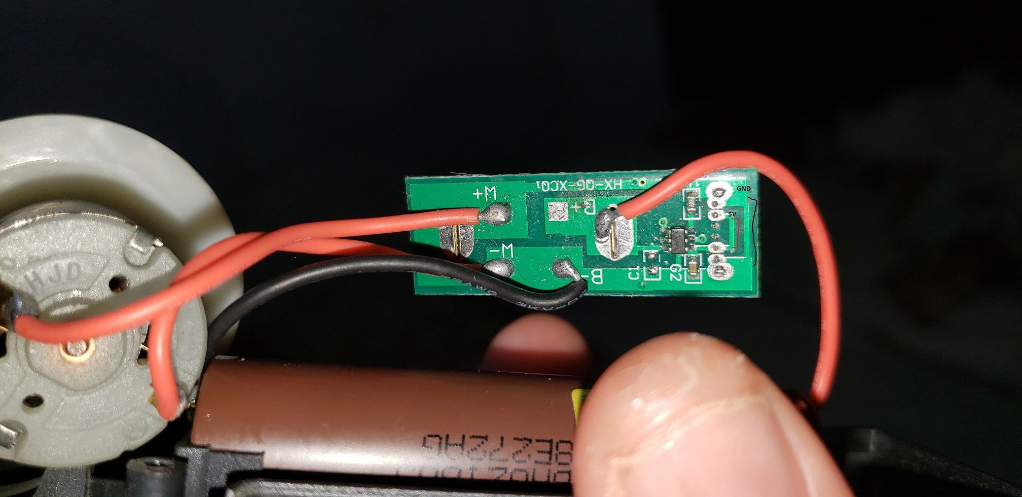
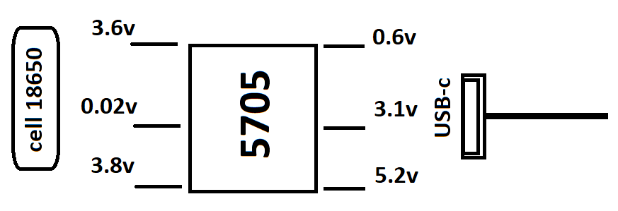
I am so novice in this kind of pcb and even although it looks very simple, I guess the problem is in the IC it says: "5705", how should I check if it's shorted or something is burned?

In M- and M+ I dont know if my multimeter is out of calibration but i reckon it measured 0 ohm (shorted)?

Images: enter image description here enter image description here enter image description here enter image description here

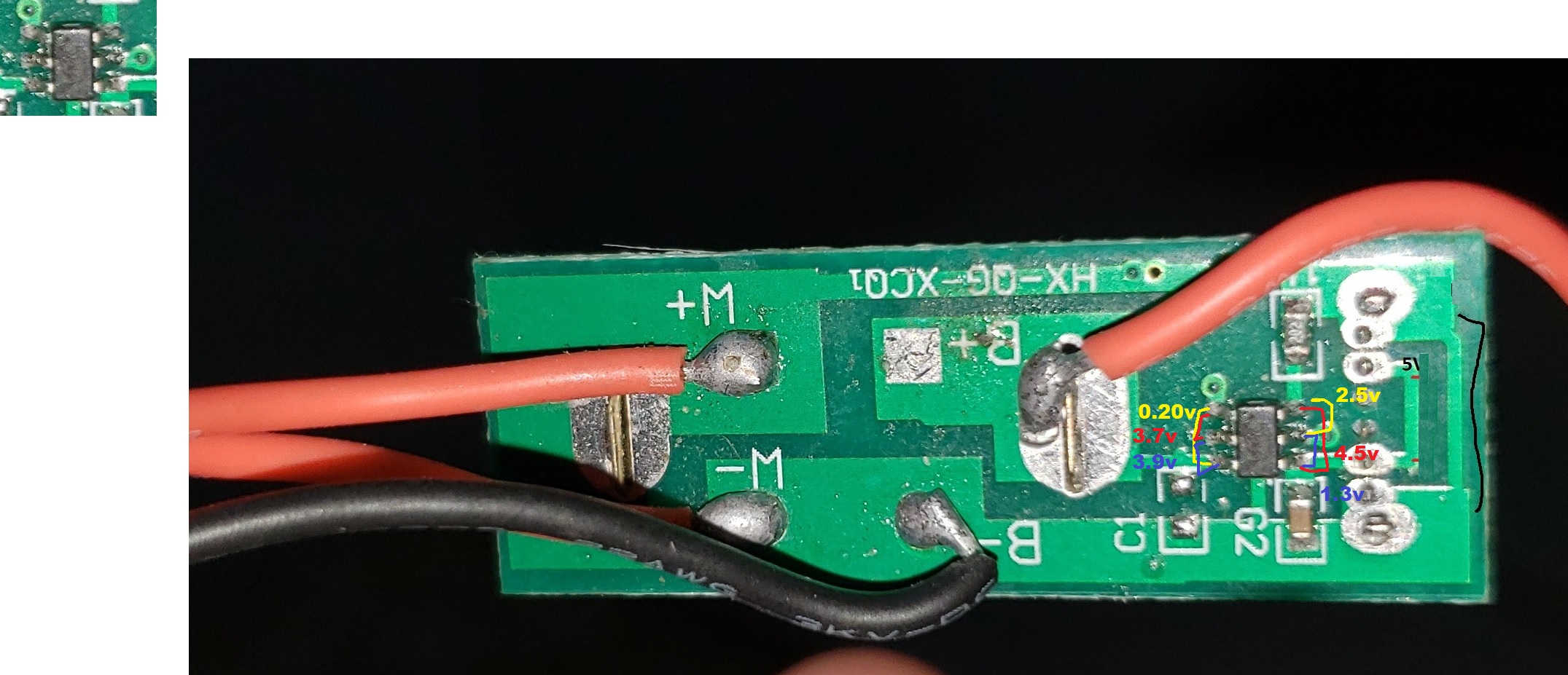
volts connected to USB CHARGER: enter image description here

enter image description here

\$\endgroup\$
11
  • \$\begingroup\$ Did you solder wires to the replacement battery (instead of spot welding them)? You might have shortened its lifespan considerably if you did. \$\endgroup\$
    – StarCat
    Commented May 26 at 7:12
  • \$\begingroup\$ Yes i 'm awared of that, but I doubt it should have something with the issue. \$\endgroup\$
    – Panamanian
    Commented May 26 at 7:15
  • \$\begingroup\$ Q1: does the motor work? Q2: When charger is connected, is there the 5V on connector pins? \$\endgroup\$ Commented May 26 at 15:02
  • 1
    \$\begingroup\$ Q3: How do you know that it is not charging? Please provide voltage measurements (since you have a DMM) on each pin of the IC when Type-C charging cable is plugged in. \$\endgroup\$ Commented May 26 at 15:25
  • \$\begingroup\$ have you verified the power supply fitness? \$\endgroup\$
    – jsotola
    Commented May 26 at 16:30

2 Answers 2

1
\$\begingroup\$

Here is the most reasonable theory of what did happen. As @nanash1 noted, the IC is likely a linear TP4057 IC. From this and PCB layout, Pin 3 is the IC output.

Now, the cell was replaced with a higher-discharge cell, which provides up to 8A current to a brushed motor. The motor is an inductor, and when the power switch is turned off, there should be enormous spikes of voltage, likely hundreds of volts. The IC likely has some protection against the spikes, but apparently not enough (and note, that C1 is omitted on the board), and after 2 month of device exploitation the IC finally broke down. This device will probably break down even if you didn't replace the cell, the design does not seem to have any snubber circuit to suppress the on-off voltage spikes, see this subject.

\$\endgroup\$
2
  • \$\begingroup\$ hundreds of volts? while running in my hand and holding the wires with my bare fingers I didnt feel anything. \$\endgroup\$
    – Panamanian
    Commented Jun 3 at 2:42
  • 2
    \$\begingroup\$ @Panamanian, bare fingers are not an exact instrument to research 100-ns wide pulses. You might not feel much, but a semiconductor junction will be fried. \$\endgroup\$ Commented Jun 3 at 4:37
0
\$\begingroup\$

We can't look inside the IC, so we can't really know what goes wrong. Top of my head, several things might be happening:

  • Damage from soldering to battery or IC
  • IC noticed that over long-time average, charging takes longer than it should for the original battery, and assumes battery damage, shuts down
  • IC was not designed for larger battery with lower internal resistance and overloaded / overheated over time
  • original battery was chosen for larger internal resistance, delivered more power than it was designed to regularly handle, and grew metal whiskers and is now damaged. IC detected that damage and won't dangerously charge it.
  • IC is OK, but device was designed with smaller battery in mind, meaning that charging cycles were shorter and hence thermal constraints less severe. Over time, any critical component might have been damaged.
  • Damage completely unrelated to the battery / charging logic; after all, this very clearly is a low-cost consumer electronics design, so reliability might have been a trade-off with production price.

Either way, I don't really see any promising path forward to repair. You should probably carefully test your battery, and design a replacement charger/control board for the powers necessary.

\$\endgroup\$
4
  • 1
    \$\begingroup\$ It's almost certainly a TP4057. The pinout matches perfectly and the 57 marking also hints in that direction (57b* is more common though). \$\endgroup\$
    – nanash1
    Commented May 26 at 11:04
  • \$\begingroup\$ @nanash1 that doesn't change at all that we can't look inside! \$\endgroup\$ Commented May 26 at 17:59
  • 2
    \$\begingroup\$ I never said it does. But it makes some of your points very unlikely, specifically 2 and 3. \$\endgroup\$
    – nanash1
    Commented May 26 at 18:24
  • \$\begingroup\$ @nanash1 that's very true! \$\endgroup\$ Commented May 26 at 18:25

Your Answer

By clicking “Post Your Answer”, you agree to our terms of service and acknowledge you have read our privacy policy.

Not the answer you're looking for? Browse other questions tagged or ask your own question.