Apologies, my electronics is a little rusty.
Wanting to measure the output of an bridge tied load amplifier and getting a little confused as what to use as the ground reference signal for the oscilloscope probes.
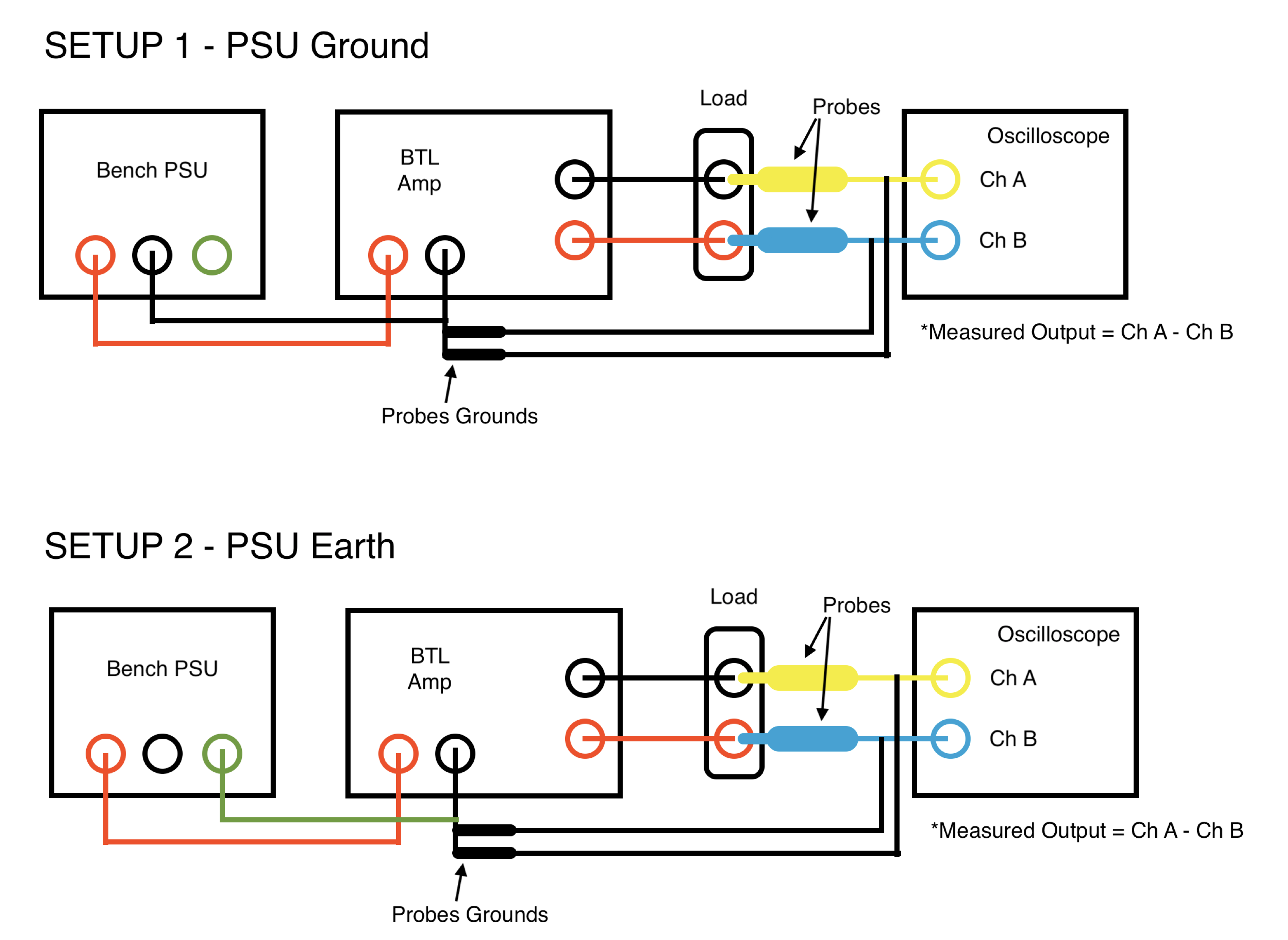
My understanding is that to measure the output of such an amplifier, given the phase inversion from each side (pos and neg) of a single output channel, requires that I have an oscilloscope probe each side of the test load, then perform an ChA - ChB maths calc to get the true output level - all makes sense (aware that I could use a differential probe but haven't got access to one unfortunately).
I'm using a benchtop PSU to power the amplifier board, where the negative line on the amplifier is connected to the negative line of the PSU, and probe ground is attached to the negative line of the amp, hence also to the negative line of the PSU (as seen in SETUP 1).
However, a number of resources I have seen suggest grounding the probe to the 'case of the amp', which would be earth. Hence, I'm not clear if this is the correct setup, and that in fact the earth line of the PSU should be connected to the negative line of the amplifier, so that the probe ground is true earth and not an isolated ground (SETUP 2)?
Or, SETUP 1 is correct, but the probe ground should be connected to the earth of the PSU (not created a diagram of this setup sorry).
Any help appreciated, thanks.
EDIT: realising that I have been a bit stupid with Setup 2, so please ignore.

