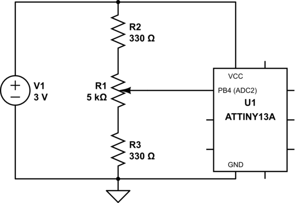
I'm making a small level meter using an ATtiny microcontroller. It uses a linear 5K potentiometer as a voltage divider coupled to an ADC pin. So far it's working except the digital values don't seem to correlate well with the measured voltage.
The schematic:

simulate this circuit – Schematic created using CircuitLab
The relevant code:
#define F_CPU 1000000
#include <avr/io.h>
#include <util/delay.h>

int adc_value;

void ADC_init()
{
    // Enable ADC
    ADCSRA |= (1 << ADEN);

    // Set ADC reference to AVCC
    ADMUX  |= (1 << REFS0);

    // Prescaler /8, 125kHz ADC sample rate @ 1MHz
    ADCSRA |= (0 << ADPS2) | ( 1 << ADPS1) | (1 << ADPS0);

    // Auto trigger enable
    ADCSRA |= (1 << ADATE);

    // Use input channel ADC2 (PB4)
    ADMUX |= (1 << MUX1) | (0 << MUX0);

    // Left shift ADC result
    ADMUX  |= (1 << ADLAR);

    // Start converting
    ADCSRA |= (1 << ADSC);
}

int main(void)
{
    DDRB = 0x07;
    PORTB = 0x00;

    ADC_init();

    while(1)
    {
        adc_value = ADCH;

        if (adc_value < 64)
            // output A
        else if (adc_value < 128)
            // output B
        else if (adc_value < 192)
            // output C
        else
            // output D
    }
}
I measured the voltage at PB4, and noted the points at which the output changed:
- Minimum: 196 mV
- 64: ~235 mV
- 128: ~500 mV
- 192: ~770 mV
- Maximum: 2.849 V
I expected approximately 1.5 V to be where a digital value of 128 is obtained, not 500 mV.
If I understand correctly, the ATtiny13A has a 10-bit ADC, the values from which are stored in two registers, ADCH and ADCL. With ADLAR (the left adjust) enabled, the value is shifted into the ADCH register and effectively two bits are discarded.
The datasheet indicates:
If the result is left adjusted and no more than 8-bit precision is required, it is sufficient to read ADCH.
I'm confused about why I am getting a nonlinear conversion on the ADC. Can you explain what I may be overlooking?

