5
\$\begingroup\$

I have the need to write a bootloader program on an AVR microcontroller (Atmega32) in order to enable self-programming. I have read various resources on the topic of bootloaders and have come to the following conclusion:

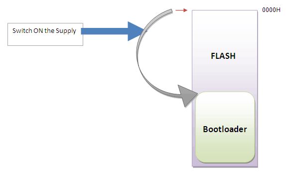
The first address of flash has stored information about where the start of the bootloader program is. Thus, when reading from flash, execution will begin at 0x00 and jump to wherever specified in that location to the bootloader.

The bootloader program must then "listen" for incoming data on a pin. If information is found, perhaps after a specific data frame consisting of a command regarding a reprogram sequence, the bootloader begins saving the incoming data to some other location in flash. Following the end of data transmission, the bootloader must then jump to the flash address associated with the first byte of information during the reprogram phase and begin execution.

It is my understanding that this sequence of events, listening and reprogramming, happens upon every RESET event. If no information is found to be incoming, then normal execution of the code already present in flash (beginning at the same address the bootloader would begin saving to) begins.

Basically something like this: enter image description here
Given that I know the process of this very basic bootloader program, where might I begin learning exactly how to write this program specifically for the AVR architecture? If size is a concern, I understand these programs may be written in ASM. Considering that I do not know enough ASM, let alone the instruction set for a given controller, I am most likely going to write this program in C.

Any suggestions/resources?

Thank you

\$\endgroup\$
1
  • \$\begingroup\$ Is there a particular reason you need to write one instead of using an existing bootloader? \$\endgroup\$ Commented Nov 8, 2013 at 3:50

3 Answers 3

5
\$\begingroup\$

Depending on your requirements there is somewhat different approach (to the common one you described) that might interest you.
You can let the main application handle the download/reception of the new firmware and "instruct" the boot loader to execute it upon reset.

To give you an idea how this could be implemented:

  1. Main application implements communication interface to receive update (USB, UART etc.)
  2. Data is stored on external memory (serial flash for example)
  3. After successful reception (checksum calculation), the main program signals the boot-loader that an update is available (write flag/update status "update available" to EEPROM for example)
  4. Main application issues software reset
  5. Boot loader reads update status information, verifies and executes the update.
  6. After the update has been completed, boot loader sets update status to "executed"
  7. Boot loader jumps to main program
  8. Main program may recognizes that an update was executed (and maybe perform some special actions) and sets the update status to "none"

In comparison to the classic approach where only the boot loader is involved:

Pros:
+ No reset required and no timing restriction to initiate update
+ Complex communication interface / protocol possible due since you are not limited to small boot section flash size
+ Better control of update mechanism
+ Decouples the communication interface from the boot loader (the reception mechanism can be updated/changed)
+ Main application "knows" about the (upcoming) update and can react (perform data migrations, configuration updates, give user feedback like "updated from v1.22 to v1.3" etc)

Cons:
- External storage required (if you never use more that half of the main flash, this could probably be abused as temporary storage)
- Slightly more complex design
- Boot loader logic is coupled to main application
- Device must be shipped with main application pre-flashed

\$\endgroup\$
3
\$\begingroup\$

The easiest way to start is to examine an existing bootloader and attempt to modify it for your needs.

On every AVR information page on Atmel's website, there is a "Documents" tab, containing information and code that Atmel provides to every visitor to their site. On the ATmega32 Documents tab there are 3 different bootloaders to examine; I recommend that you download both the PDF and the source code of all of them in order to understand how they work.

\$\endgroup\$
2
\$\begingroup\$

I wrote something like that for a AT32UC3C. Actually it was pretty easy:

  • Start by writing an application which can write some part of the flash. Try to make it as small as possible

  • Define a trigger condition (May be a button press or an inserted USB stick, depends on what you want)

  • Define a Jump Address for the main application (where the main application starts)

Now what will happen: After RESET, execution will begin at the default address (this is where your bootloader resides). The bootloader will check for a condition (button pressed, data incoming, whatever). If the condition exists, we stay in bootloader code. If the condition is NOT present (normal execution), reset any changes to registers or hardware blocks you might have made, then jump to the specified address. You can do this e.g. the following way:

    if (gpio_get_pin_value(PB_STATUS1_PIN) && !is_force_bootloader()) {
    // Run application
    void (*application)(void) = (void*)0x80008000;
    application();
}

This code will jump to address 0x80008000 -> Make sure your application is stored there.

When you're inside the bootloader - depending on how you get your data, you now have the option to write this data blockwise to flash.

Some AVRs contain an option to "protect" some area of the flash. Check where the bounds are and try to fit your bootloader into such a block. Then protect it, and even by accident you won't be able to overwrite your bootloader :-)

\$\endgroup\$

Your Answer

By clicking “Post Your Answer”, you agree to our terms of service and acknowledge you have read our privacy policy.

Not the answer you're looking for? Browse other questions tagged or ask your own question.