2
\$\begingroup\$

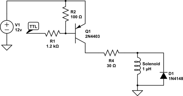
I'm trying to drive this solenoid with an inverse logic output (from a 74154).

Here's what I have in mind at the moment.
schematic

simulate this circuit – Schematic created using CircuitLab

R3 is actually the solenoid in question.

The application is an automated bell striker, so the duty cycle here is going to be very brief. Even in the most... energetic cases, I'd expect that the coil would be energized only long enough to strike the bell (I'm estimating maybe somewhere in the 50 ms range) and then it would rest for at least 500 ms, and more likely for seconds at a time.

I've simulated this, and it seems like it would work unless I am missing something stunningly obvious. With a 12 volt supply, the collector current should be around 350 mA, and the whole circuit 4.8 watts, which would give the solenoid 30 gf, if I'm reading the data sheet correctly.

Is this a stunningly terrible idea? Any other suggestions for improving it?

\$\endgroup\$
2
  • \$\begingroup\$ Is there a specific reason for using a high side switch instead of a NPN connected as a low side switch? \$\endgroup\$
    – alexan_e
    Commented Dec 23, 2013 at 21:09
  • \$\begingroup\$ If you have a solenoid in the schematic, show a solenoid. No, drawing a resistor and telling us to pretend it's the solenoid is not acceptable. Do it right. \$\endgroup\$ Commented Dec 23, 2013 at 21:19

1 Answer 1

2
\$\begingroup\$

A few things don't make sense. The page you linked to mentioned it is a 5 V solenoid, but the datasheet is in chinese and I didn't see a clear answer to what its DC resistance is. If it is really 4.5 Ω as you show, then it would draw 1.1 A at 5 V. However, with 30 Ω in series and 12 V applied, you will only get 1.6 V accross the solenoid and 350 mA will flow thru it. That would yield a lot less force. Since this solenoid has a return spring, it might not even be enough to overcome the spring.

I don't like the carefully balanced voltage divider on the base of the transistor. You seem to have done the calculations carefully enough to be a bit below the threshold when the digial signal is at 5 V, and enough to turn on the transistor when it is at 0 V. However, I'd be worried about the transistor still being partially on and leaking some current at 540 mV on its base, especially at the upper end of the temperature limit.

I guess you are going thru these contortions because the signal is inverted such that you want the solenoid on when low and off when high. My first reaction if I really needed that would be to use a digital inverter. For a few pennies, you can flip the signal and then use a more normal low side driver. Or failing that for some reason, use another transistor to solidly switch the high side driver on and off. Also, why does this solenoid need to be driven from a 12 V supply? If your 5 V supply is produced by a switcher, then it would be more efficient and easier all around to drive the solenoid from 5 V.

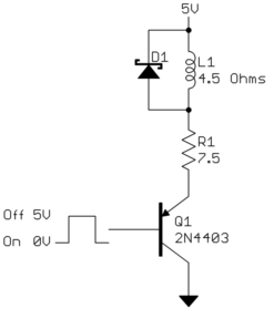
Since in this case you ultimately only want to switch the solenoid between 0 V and 1.6 V, you could use a PNP in emitter follower configuration to drive the solenoid from the 5 V supply when the base is driven low:

\$\endgroup\$
5
  • \$\begingroup\$ Thank you for that very detailed answer. It's help like that that brings me here. :) My reason for the series resistor was to limit the collector current of the transistor. Your emitter following solution is something I didn't know about (I'm primarily a software guy), and looks like the perfect solution. Thanks! \$\endgroup\$
    – nsayer
    Commented Dec 24, 2013 at 0:53
  • \$\begingroup\$ @nsayer: Note that the emitter follower as shown above will only work if you can run the solenoid from 5V. You still haven't exlained why the 12 V in your schematic. \$\endgroup\$ Commented Dec 24, 2013 at 14:24
  • \$\begingroup\$ I wanted to try and increase the power without increasing the current (which is the limiting factor for the transistor). \$\endgroup\$
    – nsayer
    Commented Dec 24, 2013 at 17:47
  • \$\begingroup\$ @nsayer: That makes no sense. Either way the solenoid will "see" only 1.6 V and 350 mA. The only difference is how much voltage appears accross other components. \$\endgroup\$ Commented Dec 24, 2013 at 18:03
  • \$\begingroup\$ Like I said... Software guy. :D When you pointed it out, it made sense. I was just answering the "why" you posed. \$\endgroup\$
    – nsayer
    Commented Dec 24, 2013 at 18:16

Your Answer

By clicking “Post Your Answer”, you agree to our terms of service and acknowledge you have read our privacy policy.

Not the answer you're looking for? Browse other questions tagged or ask your own question.