0
\$\begingroup\$

I have a situation that I've run into a few times. I have a digital output card in my system that uses SSRs. I'm trying to interface to a device (referred to as my DUT from here on) that has TTL digital inputs that are internally pulled up to 5 volts. To active the input, I need to short the input to ground.

However, using the SSR to connect the input to ground results in around 40 mV across the SSR and the DUT doesn't report this as ON.

I don't want to confuse the issue, but the DUT appears to be doing an analog measurement on the pin because there are certain functions on the DUT that are triggered by this pin being pulled low, and those functions do occur when I pull it low. However, there's a STATUS command I can send to the DUT to ask if this pin is low and it reports it as HIGH unless I actually short the input and ground with a piece of wire. This leads me to believe there are a couple different functions that query the status of this pin and that they must have different thresholds.

So my real question: is there an electrical way to minimize the voltage drop across the SSR in this scenario so the input of my DUT sees something closer to 0V?

Edit: I realize this is a hard question to answer without links to specific components, but in this case the SSR is a part of a digital output card (and thus I don't know real details about the specific implementation) and the DUT is a new device that might as well be a black box. I suspect the answer to my original question is "no" but thought I'd check to see if there was some general approach to making an SSR look a little more like a relay contact in certain specific applications.

\$\endgroup\$
4
  • 1
    \$\begingroup\$ Please share a link to the datasheet for your device under test. Without that, any answer would be mere speculation. \$\endgroup\$ Commented Jan 20, 2014 at 15:06
  • \$\begingroup\$ Also a link to the SSR used. \$\endgroup\$ Commented Jan 20, 2014 at 15:09
  • 5
    \$\begingroup\$ If a TTL input < 0.8V isn't being sensed as low, the problem lies somewhere else ... inside the DUT. \$\endgroup\$
    – user16324
    Commented Jan 20, 2014 at 15:16
  • \$\begingroup\$ @briandrummond Yeah, this is why I suspect they're doing an analog reading in the DUTand have defined their own threshold which assumes a nice, clean contact closure rather than the SSR I'm trying to use. \$\endgroup\$ Commented Jan 20, 2014 at 20:53

2 Answers 2

3
\$\begingroup\$

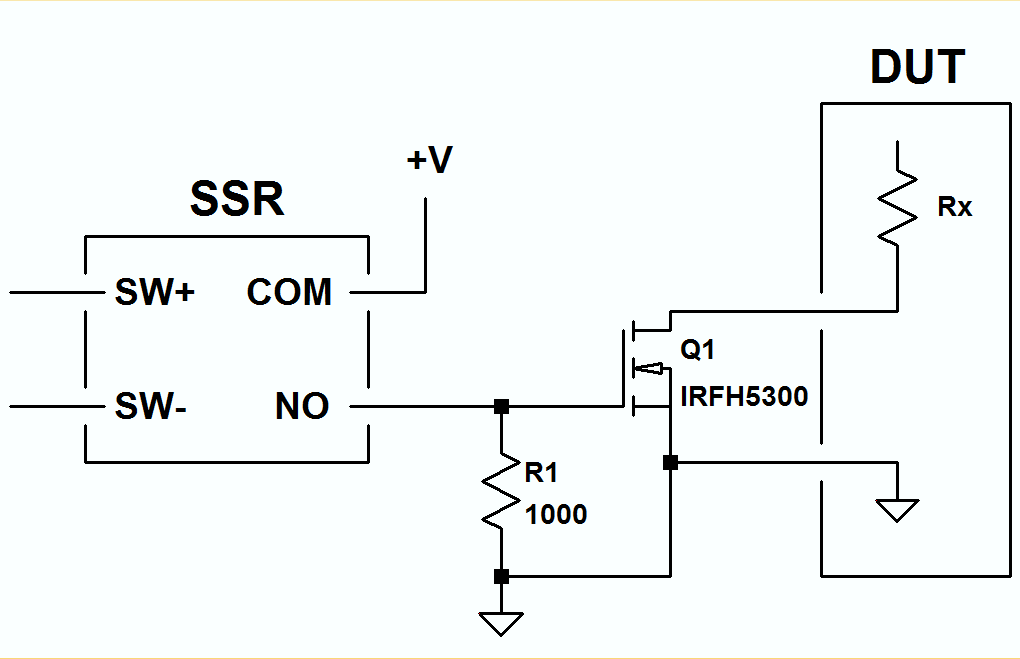
Arguably the easiest solution is to use the SSR to drive the gate of a MOSFET with a low Rds(on), and the DUT with the MOSFET's drain, like this:

enter image description here

\$\endgroup\$
1
\$\begingroup\$

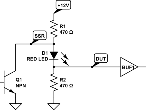
Just in case someone might have a need for a simple level shifter.

This circuit will offer 5V high and 0V low with an impedance of under 500Ohms. It will have a drive capacity of almost 8mA. None of these are really to TTL specification but should be adequate to fool an analogue input into thinking it is connected to a 0-5V digital output. It should be enough to drive one standard LSTTL load or a CMOS input or a analogue input pin on a Microcontroller.

It does assume that the SSR output is open collector or drain and happy with switching of 7V. The circuit operation is simple, the LED (2V) and resistors (5V+5V) form a potential divider with about 10mA current flowing through it when the SSR is open. When the SSR closes it pulls the supply resistor near ground (well below the forward voltage of the LED) and the pull down resistor will then draw the output pin to ground with 470 Ohm.

schematic

simulate this circuit – Schematic created using CircuitLab

This answer is in part my experimentation with the schematic capture plugin that seems kind of nice and requires no user manual.

\$\endgroup\$
2
  • \$\begingroup\$ If the DUT input looks like 10k ohms pulled up to 5V, then 470 ohms will pull it [the DUT input] down to 224 millivolts, so that won't work. \$\endgroup\$
    – EM Fields
    Commented Oct 27, 2014 at 20:40
  • \$\begingroup\$ @EMFields Very true. The 40mV threshold is very demanding. If one needed only a couple, an active buffer made to switch a few mV below ground should work. Replacing LED with bigger diodes in series would allow the divider current to be increased to the SSR handling capacity. It it can switch 1A then the pull-down resistor could be a 5W 5Ohm resistor with a 10kOhm pull-up it would only have 2mV showing, that would be 1 LSB in a 9 bit A/D input. All round a poor design if it needs a short to ground to detect an input unless it is an actual wire break security feature of some sort. \$\endgroup\$
    – KalleMP
    Commented Oct 28, 2014 at 10:56

Your Answer

By clicking “Post Your Answer”, you agree to our terms of service and acknowledge you have read our privacy policy.

Not the answer you're looking for? Browse other questions tagged or ask your own question.