2
\$\begingroup\$

I am trying to hack a personal weighing scale.I had taken help of this tutorial but the language used in this is not very easy to understand due to the non-standard naming used for load sensor wires, but its a good tutorial. I had also looked at this tutorial to have a good understanding of adding a strain gauge in whetstone bridge in order to measure small change in resistance.

Also the amplifier used in the tutorial is not easily available in India i.e. INA125.

My question is , is there any alternative for the amplifier INA125.

Also i had read certain other tutorials for adding load sensor to the INA125 , but wasn't able to figure out exactly how to do it?

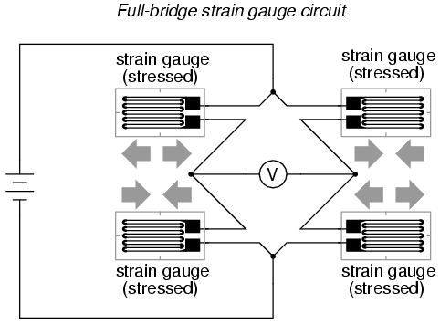
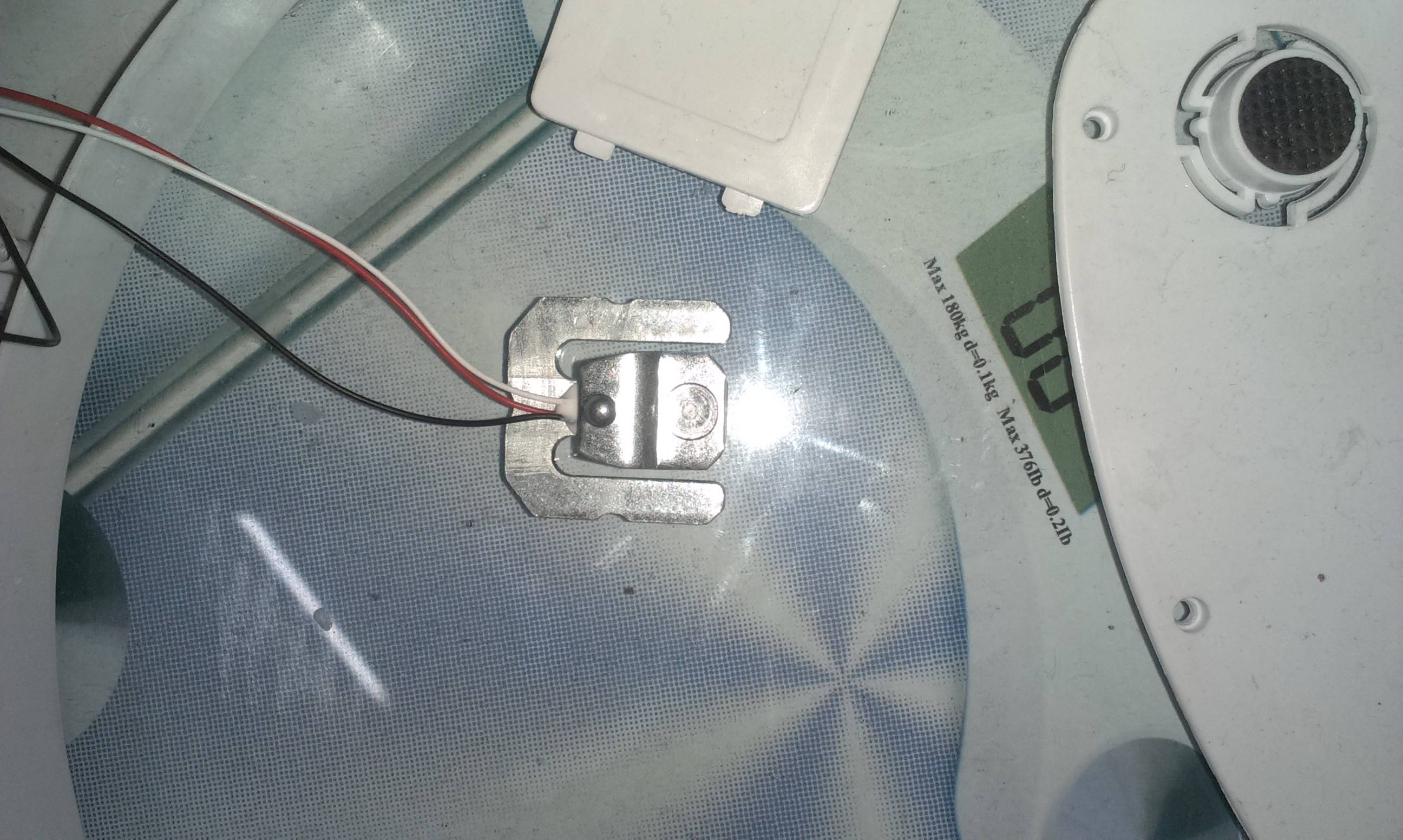
When i looked at this tutorial, i find that load sensor has to be added in place of resistors in Wheatstone bridge, but every load sensor has 3 wires, now which 2 wires has to be added in Wheatstone bridge,in order to make a full bridge circuit like this Full bridge circuit with strain gauge. I had even looked at a similar question but didn't get the answer.
I am enclosing images of the load sensor and weighing machine which i am using.My main aim is to read the load sensor readings with Arduino for a different project. Load sensor wires Personal weighing scale
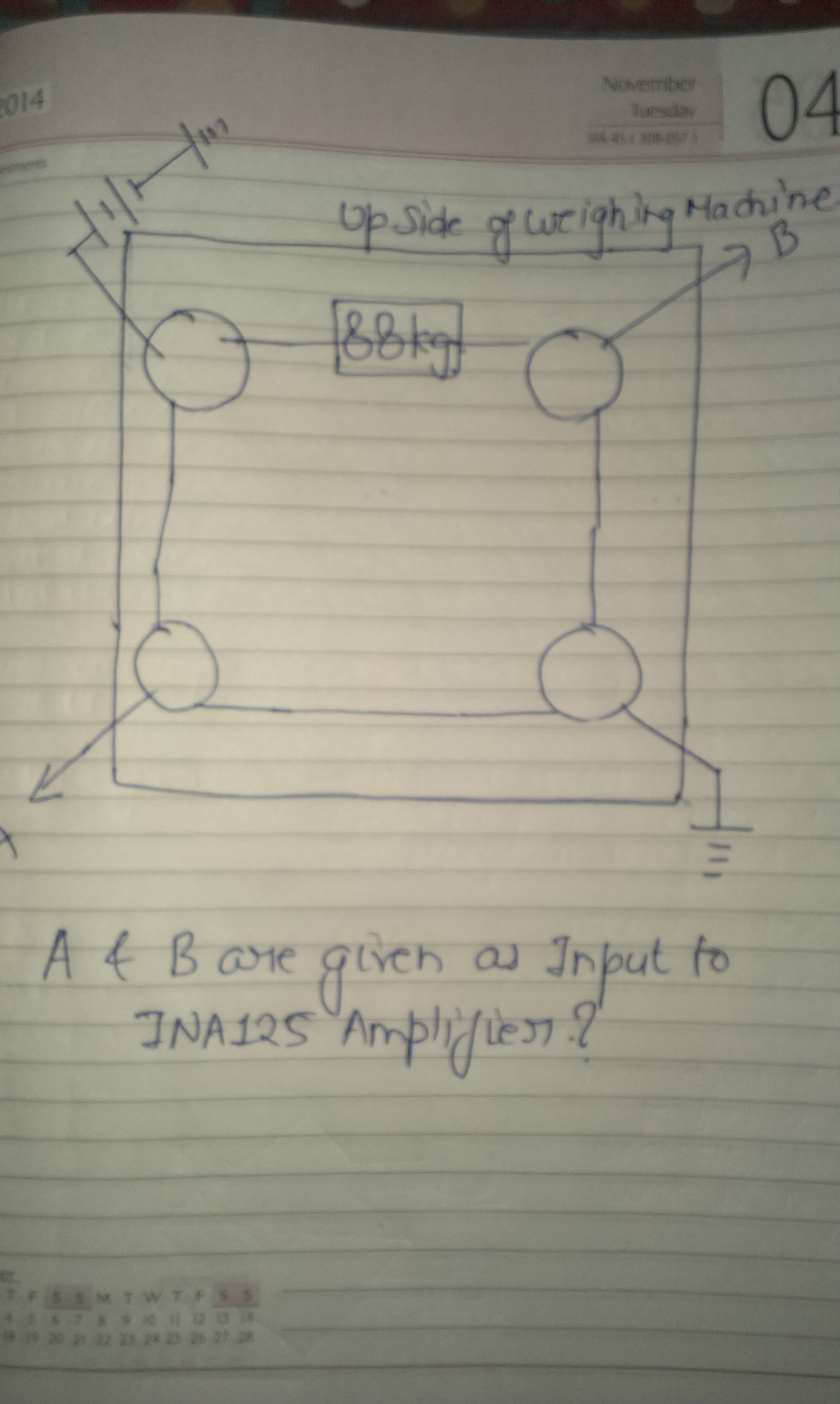
I had came up with a possible interface of the 4 load sensors to INA125 amplifier, can some body verify this?Below is the image. possible interface In this A and B will be connected to the pin no 6 and 7 i.e. VIn + and VIn -
\$\endgroup\$
7
  • \$\begingroup\$ A three wire sensor is probably two of the sensors shown in your diagram. You can check this by measuring the resistances \$\endgroup\$
    – Andy aka
    Commented Mar 22, 2014 at 16:59
  • \$\begingroup\$ @Andyaka : ok, those 2 wires can be fined out by measuring the resistance, is they need to be placed in specific places in Wheatstone bridge.I am updating my question with respect to the connection between 4 load senors in order to put them in Wheatstone bridge and give its output to the INA125. \$\endgroup\$
    – shailendra
    Commented Mar 22, 2014 at 18:45
  • 1
    \$\begingroup\$ See electronics.stackexchange.com/questions/102164/… and in particular a link provided there to nerdkits.com/forum/thread/900 and a comment made by mrobbins on August 16, 2010. It may help some regarding 3-wire arrangements. \$\endgroup\$
    – jonk
    Commented Mar 22, 2014 at 21:16
  • \$\begingroup\$ Please clarify your question. Is it the original "what can I replace an INA125 with?", or is it a new question regarding how to wire up 4 load sensors of your particular scale to get a voltage reading suitable for an Arduino, or is it how to detect a person standing on a scale? \$\endgroup\$
    – gwideman
    Commented Apr 17, 2014 at 12:22
  • \$\begingroup\$ To pursue the "how to wire these four sensors" I think you'll need to figure out how the sensors behave. Do the 3 wires correspond to two active sections of strain gauge, or to two separate strain elements (one on top and one underneath the strain beam), or is one element inactive but present for temperature compensation, etc. It would be helpful to measure their resistance change under weight, which probably requires wiring up a temporary bridge (to convert resistance to voltage) to make some measurements. \$\endgroup\$
    – gwideman
    Commented Apr 17, 2014 at 12:25

1 Answer 1

2
\$\begingroup\$

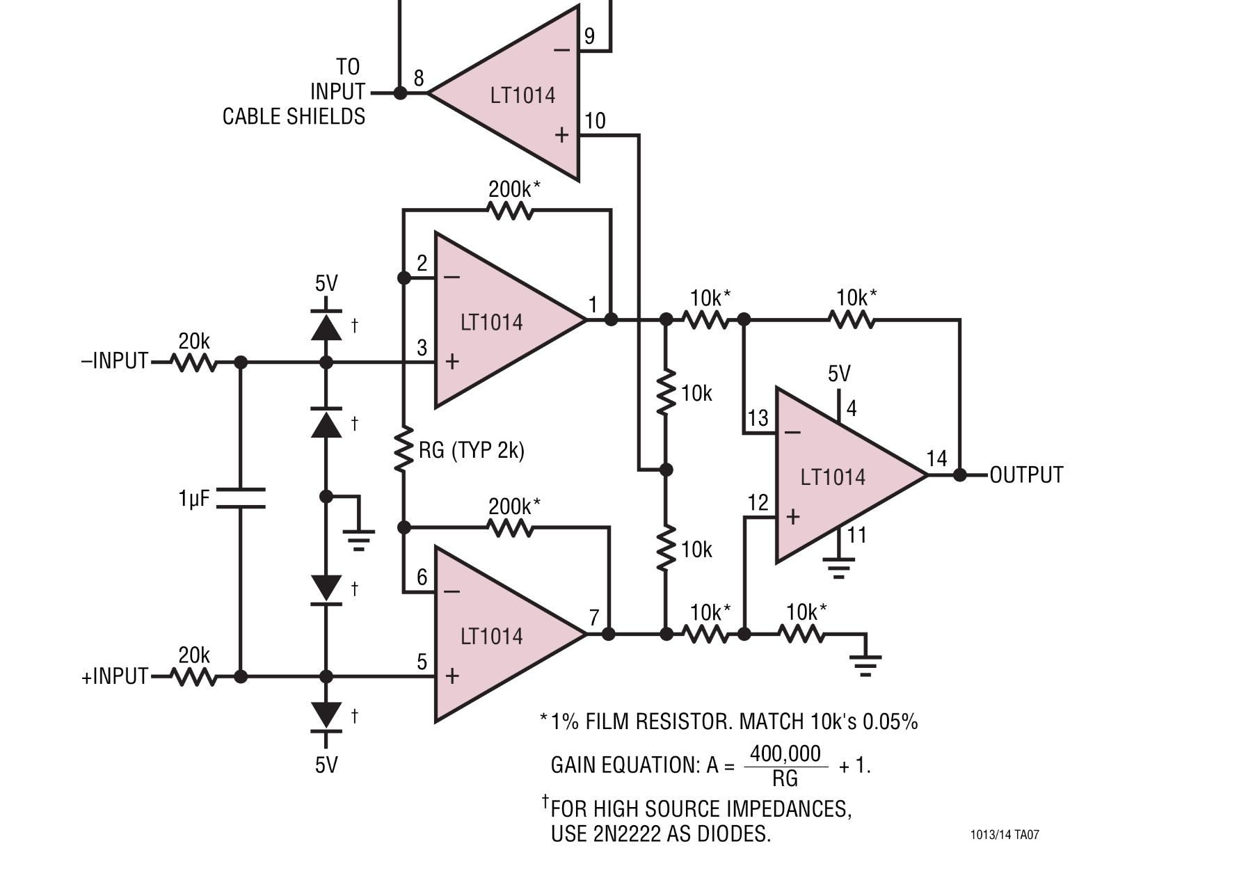
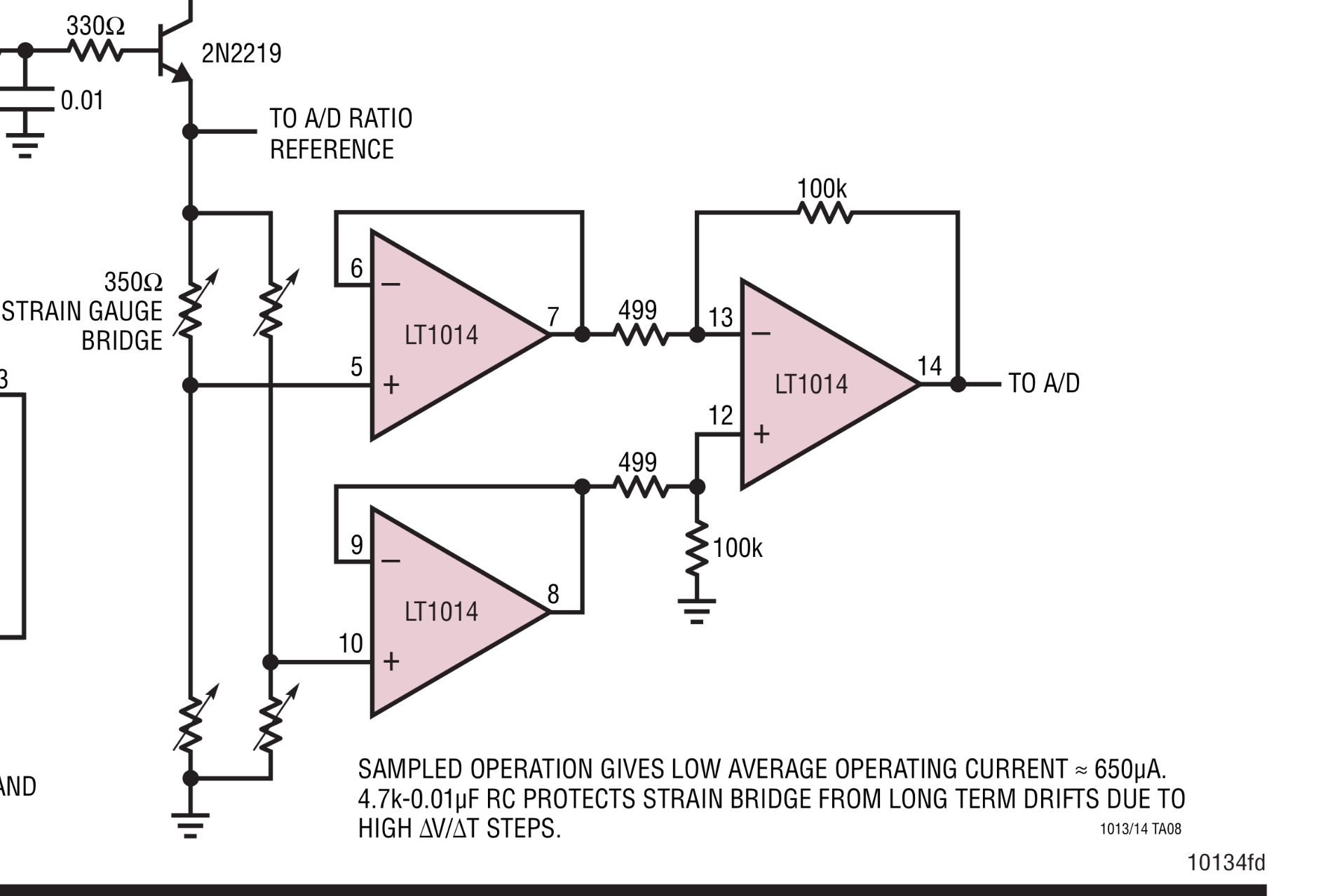
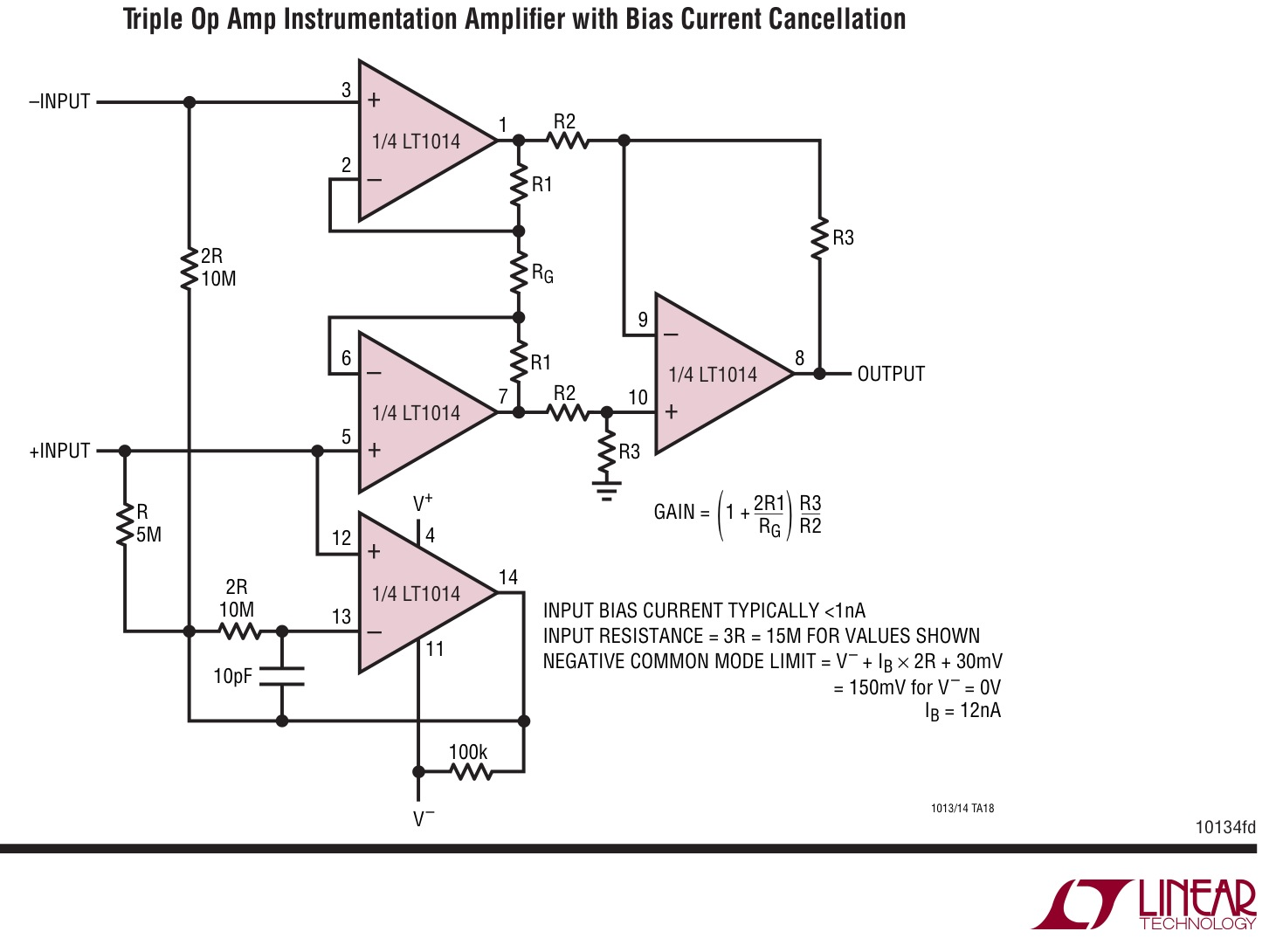
The INA125 is a convenient Instrument Amplifier with a Voltage reference. Alternatives could use any 3 suitable Op Amps in an IA configuration with suitable ref. voltage buffered by a 4th OpAmp using a quad OA, such as LM324.

Depending on wiring length and common mode noise around will determine how high CMMR you need offered by IA designs. Often with low impedance bridges, you can get away without much gain or extra high CMRR.

Here are some examples;

enter image description here

The two sensors are likely half bridges with 3 wires used for left and right side of bridge, which is symmetrical and the centre tap is probably the middle wire.

enter image description here

enter image description here

\$\endgroup\$
4
  • \$\begingroup\$ Doesn't answer the question... \$\endgroup\$
    – Matt Young
    Commented Apr 14, 2014 at 19:21
  • \$\begingroup\$ Which one? I answered this one. "My question is , is there any alternative for the amplifier INA125." \$\endgroup\$
    – user38637
    Commented Apr 14, 2014 at 19:25
  • \$\begingroup\$ I find it reasonable enough to use the OP-amp separately but why to use them when you already have a chip designed for this purpose. \$\endgroup\$
    – shailendra
    Commented Apr 18, 2014 at 14:09
  • \$\begingroup\$ I dont know what the OP needs to learn. How to make a bridge work? Or How to make a differential amp work? Both are fundamental and easy to find how-to .. electronics-tutorials.ws/blog/wheatstone-bridge.html The IA simply rejects CM noise better converting to a single ended output \$\endgroup\$
    – user38637
    Commented Apr 18, 2014 at 16:31

Your Answer

By clicking “Post Your Answer”, you agree to our terms of service and acknowledge you have read our privacy policy.

Not the answer you're looking for? Browse other questions tagged or ask your own question.