1
\$\begingroup\$

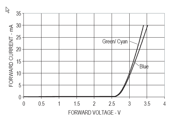
I would like to drive a 3x3 RGB LED matrix multiplexed. This means each RGB LED has 1/9 duty cycle and that means it consumes 1/9 of total current. The RGB LED I am using is designed for max 35 mA continuous forward current that means: 35 / 9 = 3.8 mA for each LED which isn't very bright. Its peak forward current is specified at 1/10 duty cycle, 0.1 ms pulse width and max. 100 mA. The datasheet gives me this diagram to determine the forward voltage:
enter image description here

As you can see on the Y axis the maximum current is 35 mA. How am I supposed to determine the forward voltage for 100 mA?

Complete Datasheet: http://www.csd-electronics.de/data/pdf/LL-509RGBC2E-006.pdf

\$\endgroup\$

3 Answers 3

5
\$\begingroup\$

The 100mA/10% duty cycle is absolute maximum rating at 25°C ambient temperature. It is not something you should be designing to, and note that it only gives you 10mA average current per LED. It should be derated significantly (let's say 30%, 40% or more) to allow for ambient greater than 25°C and to avoid the absolute maximum limit. At 40% derating, you can estimate by simply extrapolating the curves. Straight line extrapolation will be a bit pessimistic, so maybe use a French curve (I'm sure you can download the shape and cut it out if you don't have one in your desk drawer).

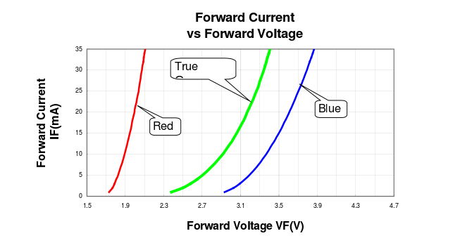
Note carefully: This part uses really small (and therefore cheap) LED dies, as evidenced by the rather large forward voltages at moderate currents. Compare other LEDs from suppliers with full datasheets to see the differences (below is an Avago curve for a similar 472nm (blue) LED).

Thus, it's not really that suitable for multiplexed use unless you don't need a lot of brightness. With static drive you can get tens of mA reliably, with 11% duty cycle, maybe 7 or 8mA average safely.

It has been suggested that you try to characterize samples yourself, if you try to do that you MUST pulse the current both to keep from frying the LED and to avoid the effects of the temperature coefficient of the LED die.

Avago blue LED:

enter image description here

\$\endgroup\$
4
\$\begingroup\$

You can't determine the forward voltage at 100 mA from the datasheet. Also, keep in mind that the graph shows typical values rather than maximum values. The datasheet is also misleading in specifying 35 mA continuous current, because you would violate the maximum continuous power specification at that current for the green and blue LEDs.

You could characterize the devices yourself to determine the range of forward voltages at 100 mA, and then use this information to design an appropriate constant-current supply.

\$\endgroup\$
4
\$\begingroup\$

If accuracy is important, consider using a current drive circuit (i.e. constant current source) to power each LED rather than the basic method of placing a resistor in series with a voltage source. You can find a basic current source here. If you use a current source you won't need to worry about variations in the forward voltage and temperature affecting the current in the LED.

If a constant current source is too complicated, you can approximate the forward characteristic of the diode using a pieceweise linear model, ie. a forward voltage plus a resistance. See the example here. From this it should be straighforward to get the current at 100mA.

\$\endgroup\$

Your Answer

By clicking “Post Your Answer”, you agree to our terms of service and acknowledge you have read our privacy policy.

Not the answer you're looking for? Browse other questions tagged or ask your own question.