1
\$\begingroup\$

I'm learning PIC (pic18f4550) and pretty new to microcontroller programming. I'm trying get value of three button on PORTA and send it to a 8x8 led matrix as X coordinates through a 74LS595. The problem is that the value go to the led matrix doesnt change when i pressed the buttons to create different value. I'm simulating on Proteus so I guess I don't need debounce function. Here's my code and schematic:

#include<p18f4550.h>

#define SCK LATBbits.LATB0
#define DATA PORTBbits.RB1
#define SCL PORTBbits.RB2

void Data_in(unsigned char k){
    DATA=k;
    SCK=0;
    SCK=1;
}

void LatchData(){
    SCL=0;
    SCL=1;
}

void Send1byte(unsigned char data)
{
    unsigned char i,temp;
    for(i=0;i<8;i++)
    {
        temp = data & (1<<i);
        if(temp)
        {
            DATA = 1;
        }
        else
        {
            DATA = 0;
        }

        SCK = 0;
        SCK = 1;
    }

SCL = 0;
SCL = 1;
}

unsigned char getMatrixX(unsigned char in_X)
{

    switch(in_X)
    {
        case 0:      // the value stuck here
        return 0b01111111;
    case 1:
        return 0b10111111;
    case 2:
        return 0b11011111;
    case 3:
        return 0b11101111;
    case 4:
        return 0b11110111;
    case 5:
        return 0b11111011;
    case 6:
        return 0b11111101;
    case 7:
        return 0b11111110;
    default:
        return 0b11111111;
    }
}

void main()
{

    TRISA = 1;
    TRISC = 1;

    TRISB = 0;
    TRISD = 0;

    PORTD = 0x80;

    while(1){
        Send1byte(getMatrixX(LATA));
    }
}

This is link to my schematic: my Schematic

Really appreciate any solutions and advices. Sorry for my bad english.

\$\endgroup\$
5
  • 2
    \$\begingroup\$ For one thing, in the switch() statement, you need a break; at the end of each case. \$\endgroup\$ Commented May 23, 2014 at 18:25
  • 3
    \$\begingroup\$ thank you for advice, but still not work, besides, due the return instruction, i don't think a break is neccessary \$\endgroup\$ Commented May 23, 2014 at 18:46
  • 1
    \$\begingroup\$ You're right, break is unnecessary here. \$\endgroup\$
    – Dzarda
    Commented May 23, 2014 at 19:05
  • \$\begingroup\$ what kind of buttons do you have? According to the schematic, the inputs to the processor will get pulled ~LOW~ when the button is closed (pressed?). \$\endgroup\$
    – Adam Head
    Commented May 23, 2014 at 19:16
  • \$\begingroup\$ Adam, it's just normal push button, Proteus allow me to keep it pressed or unpressed during simulation, so yes, it is low when pressed and high when not pressed, I use those states to create value, to read from \$\endgroup\$ Commented May 23, 2014 at 19:20

2 Answers 2

4
\$\begingroup\$

There are a number of things that need fixing in your code before we can start to assist with the functional problems. I have listed a few below.

Use of TRIS

Please see the answer from Handoko, which deals with this.

Use of LAT vs. PORT registers

You call your function like this: Send1byte(getMatrixX(LATA)). I assume your intention is to get the current status of the input buttons and send them to this function.

This will not work, you need to read from the PORTA register instead. The correct code would read Send1byte(getMatrixX(PORTA)).

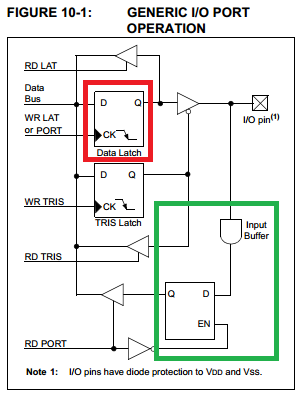
Why is this? There is a short explanation in the datasheet:

Reading the PORTA register reads the status of the pins; writing to it will write to the port latch.

And a helpful image:

Figure 10-1 PORT vs. LAT

The internal data line which is used when you read the PORT bit (bottom left, from the green block) is connected to the input buffer, which comes directly from the I/O pin. In contrast the data line used when you read the LAT bit (top left, connected to the red block) only reads the status of the data latch. It is not connected to the input.

Note that the SCK/DATA/SCL definitions should work (writing to the PORT bit will set the LATch) but I usually keep all writes to the LATch except where impossible (e.g. bidirectional busses).

Configuration of analogue functions

You need to disable the analogue functions which are multiplexed onto PORTA pins. See this note from the datasheet:

On a Power-on Reset, RA5 and RA3:RA0 are configured as analog inputs and read as ‘0’. (section 10, page 113)

In addition the comparator function also needs to be disabled. To set all PORTA pins to digital inputs, see Register 21-2 (ADCON1) in the datasheet. You might try:

ADCON1 = 0x0F; // All digital inputs
CMCON = 0x07;  // Comparators off (note this is the POR default)

If you don't do this then you will never get the input data from your switches, unless the Proteus simulator does unusual things.

Simplifying getMatrixX()

You could simplify your getMatrixX() function in a number of ways, depending if you care about code or data space. Here's one which uses a table lookup (untested):

unsigned char data[8] = { 0b01111111, 0b10111111, 0b11011111, 0b11101111, 0b11110111, 0b11111011, 0b11111101, 0b01111110 };

unsigned char getMatrixX(unsigned char in_X) {
  if (in_X > 7) {
    return 0xFF;
  }

  return data[in_X];
}

It would be simple to do the same thing with a shift and some logic, avoiding the lookup table:

unsigned char getMatrixX(unsigned char in_X) {
  if (in_X > 7) {
    return 0xFF;
  }

  return 0xFF ^ (0x80 >> in_X);
}
\$\endgroup\$
2
  • \$\begingroup\$ Super answer David, it worked, it really worked! The analogue function is the problem, your LAT explantion and lookup table also helps me a lot, dind't understander it until now. You just save my day, will give you a vote when I have enough reputation \$\endgroup\$ Commented May 23, 2014 at 19:54
  • \$\begingroup\$ Glad it helped. Always check out the section in the datasheet titled "SUMMARY OF REGISTERS ASSOCIATED WITH PORTA", for example Table 10-2 for the PIC 18F4550. This can be very helpful in tracking down other functionality that needs turning off. \$\endgroup\$
    – David
    Commented May 23, 2014 at 19:56
4
\$\begingroup\$

First of all you need to configure your input and output correctly.

You used TRISA = 1; which means only RA0 is an INPUT. Please change this to TRISA = 0b00000111; or TRISA = 0x07; to configure all 3 buttons as INPUT.

Same counts for TRISB. Change this value to 0x00000111 or 0x07.

As Peter has mentioned change all your cases on the switch to:

case1:
 // TODO
 return;
case2:
 // TODO
 return;

Besides, I don't even see where you scripted what the MCU has to do when a button is pressed?

\$\endgroup\$
6
  • 2
    \$\begingroup\$ +1 for the bit pattern problem. That said, please edit your answer - break; is redundant when return; is present in the case: statement. \$\endgroup\$
    – Dzarda
    Commented May 23, 2014 at 19:09
  • \$\begingroup\$ thanks for answering, I tried TRISA = 0xFF and 0x07 already, it doeasn't work, besides, as I comment, I already had return, it returned me a value and get out of the function, so I don' think I need breaks. About the buttons, i meant to get just the value from it, so I put the LATA into the getMatrixX function as you can see (proteus allow me to keep the button pressed or unpressed) \$\endgroup\$ Commented May 23, 2014 at 19:14
  • 1
    \$\begingroup\$ On the enhanced PICs you should read from a PORT, write to a LATch. \$\endgroup\$
    – David
    Commented May 23, 2014 at 19:15
  • \$\begingroup\$ @David Thats precisely the point I was going to make. I'm not familiar with PICs, but LATCH is supposed to be output right? Can you even read from that? \$\endgroup\$
    – Dzarda
    Commented May 23, 2014 at 19:19
  • 2
    \$\begingroup\$ You can read from the LATx register but you will just get the value that has been set for the output latch. If a pin is set to input in the TRISx register then the value in the PORTx is the correct thing to read for inputs. \$\endgroup\$
    – David
    Commented May 23, 2014 at 19:21

Your Answer

By clicking “Post Your Answer”, you agree to our terms of service and acknowledge you have read our privacy policy.

Not the answer you're looking for? Browse other questions tagged or ask your own question.