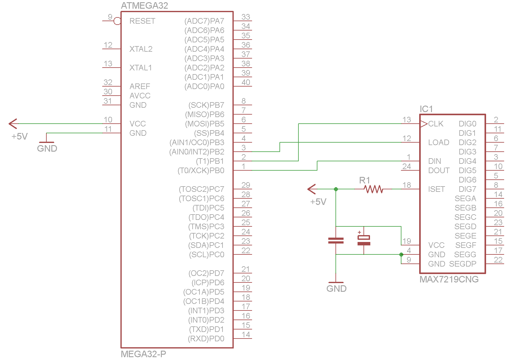
I'm trying to use an ATmega32 to communicate to a MAX7219 chip for multiplexing with an led matrix. However, I do have multiple different devices that I want to communicate with.
I am trying to communicate with the device without actually using the SPI pins provided on the microcontroller. I have made a test project, but nothing is working. At first it seemed there was something wrong with my code. I've been on other forums and people have shown me better code for doing the job, but still I can't seem to get this working. I've checked all my wiring and even connected it to an Arduino and it ran perfectly. So now I'm thinking it has something to do the the ATmega. Do any pins need pull-up or pull-down resistors on them? Or is there maybe something else that is the issue?

here is just a lazy test. Not even this works, test nor shutdown. simple test code:
//test

#include <avr/io.h>

int main(void)
{
DDRB = 0b00000111; // pin 1, 2 and 3 are outputs
/*
//display test
PORTB = 1 << PINB0; // data pin 1 is high
PORTB = 0 << PINB1; // clock pin 2 is low
PORTB = 0 << PINB2; // latch pin 3 is low

PORTB = 1 << PINB1; // clock pin is high
PORTB = 0 << PINB1; // clock pin is low

PORTB = 1 << PINB1; // clock pin is high
PORTB = 0 << PINB1; // clock pin is low

PORTB = 1 << PINB1; // clock pin is high
PORTB = 0 << PINB1; // clock pin is low

PORTB = 1 << PINB1; // clock pin is high
PORTB = 0 << PINB1; // clock pin is low

PORTB = 1 << PINB1; // clock pin is high
PORTB = 0 << PINB1; // clock pin is low

PORTB = 1 << PINB1; // clock pin is high
PORTB = 0 << PINB1; // clock pin is low

PORTB = 1 << PINB1; // clock pin is high
PORTB = 0 << PINB1; // clock pin is low

PORTB = 1 << PINB1; // clock pin is high
PORTB = 0 << PINB1; // clock pin is low

// next 8 bits

PORTB = 1 << PINB1; // clock pin is high
PORTB = 0 << PINB1; // clock pin is low

PORTB = 1 << PINB1; // clock pin is high
PORTB = 0 << PINB1; // clock pin is low

PORTB = 1 << PINB1; // clock pin is high
PORTB = 0 << PINB1; // clock pin is low

PORTB = 1 << PINB1; // clock pin is high
PORTB = 0 << PINB1; // clock pin is low

PORTB = 1 << PINB1; // clock pin is high
PORTB = 0 << PINB1; // clock pin is low

PORTB = 1 << PINB1; // clock pin is high
PORTB = 0 << PINB1; // clock pin is low

PORTB = 1 << PINB1; // clock pin is high
PORTB = 0 << PINB1; // clock pin is low

PORTB = 1 << PINB2; // latch pin 3 is high

*/

// shutdown
PORTB = 1 << PINB0; // data pin 1 is high
PORTB = 0 << PINB1; // clock pin 2 is low
PORTB = 0 << PINB2; // latch pin 3 is low

PORTB = 1 << PINB1; // clock pin is high
PORTB = 0 << PINB1; // clock pin is low

PORTB = 1 << PINB1; // clock pin is high
PORTB = 0 << PINB1; // clock pin is low

PORTB = 1 << PINB1; // clock pin is high
PORTB = 0 << PINB1; // clock pin is low

PORTB = 1 << PINB1; // clock pin is high
PORTB = 0 << PINB1; // clock pin is low

PORTB = 1 << PINB1; // clock pin is high
PORTB = 0 << PINB1; // clock pin is low

PORTB = 1 << PINB1; // clock pin is high
PORTB = 0 << PINB1; // clock pin is low

PORTB = 1 << PINB0; // data pin is low

PORTB = 1 << PINB1; // clock pin is high
PORTB = 0 << PINB1; // clock pin is low

PORTB = 1 << PINB1; // clock pin is high
PORTB = 0 << PINB1; // clock pin is low

// next 8 bits

PORTB = 1 << PINB1; // clock pin is high
PORTB = 0 << PINB1; // clock pin is low

PORTB = 1 << PINB1; // clock pin is high
PORTB = 0 << PINB1; // clock pin is low

PORTB = 1 << PINB1; // clock pin is high
PORTB = 0 << PINB1; // clock pin is low

PORTB = 1 << PINB1; // clock pin is high
PORTB = 0 << PINB1; // clock pin is low

PORTB = 1 << PINB1; // clock pin is high
PORTB = 0 << PINB1; // clock pin is low

PORTB = 1 << PINB1; // clock pin is high
PORTB = 0 << PINB1; // clock pin is low

PORTB = 1 << PINB1; // clock pin is high
PORTB = 0 << PINB1; // clock pin is low

PORTB = 1 << PINB2; // latch pin 3 is high
}

_delay_ms()s commented out? \$\endgroup\$