1
\$\begingroup\$

The voltage source has a specific voltage through it regardless of the circuit's current and its resistance while the current source has a specific current through it regardless of the voltage through it and its resistance.

My question is:

When there's a circuit which has both a voltage source and a current source with a load, a resistor R for example. How can people apply Ohm's law on it. The sum of both voltage and current must be reserved.

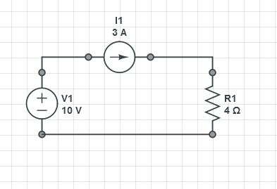
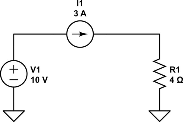
For example, the circuit has a current source and a voltage source connected in a series with a single resistor which

  • The voltage source supply 10V
  • The current source supply 3A
  • The resistance of the resistor is 4 ohm. enter image description here
How can Ohm's law be applied in this case.

If we take 10V then the current will be 2.5A which is lack of 0.5 A to make the sum of current equal 3 as the current source supply while if we take the current through it is 3 A then the voltage through it wil be 12 V that over the one which voltage source can supply. I have seen many circuit which have both of these source without knowing how to apply Ohm's law on it.

\$\endgroup\$
2
  • \$\begingroup\$ Can you add a schematic for such a circuit? \$\endgroup\$
    – Amit Hasan
    Commented Sep 16, 2014 at 13:51
  • 2
    \$\begingroup\$ 12 volts across the resistor and -2V across the current source. \$\endgroup\$
    – Andy aka
    Commented Sep 16, 2014 at 14:30

5 Answers 5

4
\$\begingroup\$

This only answers one part of your question, but I think it might be the main place where you are misunderstanding.

How can the Ohm Law be applied in this case?

"Ohm's Law" isn't a law for all circuits. It's a description of one particular type of component: the ideal linear resistor.

It doesn't matter how your power supplies are arranged in your circuit. Ohm's law has nothing to do with power supplies.

The general laws you want to consider that describe how currents and voltages relate in any circuit are Kirchoff's Current Law and Kirchoff's Voltage Laws. These laws, along with specific current-voltage relationships for each type of device (one of which is Ohm's Law), are the main tools for analyzing circuits.

\$\endgroup\$
3
\$\begingroup\$

Well, in practice, a current source is a voltage source that adjusts itself to send said current, so if you build one of those in real life, the voltage source will try to apply 3A in the resistor, for that to happen, the voltage running in the resistor would be V=3*4=12, but 10v are already coming from the voltage source, so the voltage the CS would apply should be 2v. This way, the 10V of the VS + the 2V of the CS could make the 12V, that 12/4 = 3A.

\$\endgroup\$
2
\$\begingroup\$

I understand the circuit you propose is like Fig.

schematic

simulate this circuit – Schematic created using CircuitLab

It can be solved by applying the principle of superposition.

First, solve for the voltage source, current source passivated. In this particular case, passivating the current source, the voltage applied to the load is zero, and that is in open circuit.

Secondly, solving for the current source should passivate the voltage source (replace it for a short-circuit). This allows us to calculate the voltage across the resistor as:

$$ V_R = I\cdot R = 3\cdot 4 = 12\mathrm{V} $$

This is consistent with the physical characteristics of a voltage source (low output impedance) and a current source (high output impedance). In practice, the voltage source should be capable of supporting the current set by the current source.

\$\endgroup\$
4
  • \$\begingroup\$ it look more like this i.imgur.com/F6FwwQF.png . Still, I don't understand why in 1st case it is open circuit \$\endgroup\$
    – aukxn
    Commented Sep 16, 2014 at 15:15
  • \$\begingroup\$ @aukxn I do not see the difference between the schemes ... However, passivation is the current source for the first case. Passivating a current source corresponds to replace it with an open circuit. Analyzing the circuit in this condition, there is no voltage present on the resistor. \$\endgroup\$ Commented Sep 16, 2014 at 15:26
  • \$\begingroup\$ Sorry, I'm not native english speaker, the word "passivation" is too hard for me to understand. Can you explain it in other word? \$\endgroup\$
    – aukxn
    Commented Sep 16, 2014 at 15:27
  • \$\begingroup\$ @aukxn "Passivation" means nullify the effects of that source. This is necessary to apply the principle of superposition, where it is analyzed separately the effect of each source in the circuit. \$\endgroup\$ Commented Sep 16, 2014 at 15:31
1
\$\begingroup\$

Note that a voltage source's impedance (internal resistance) is zero Ohm (ideal) and a current source's impedance is infinity (ideal).

So in a circuit, replacing a voltage source with a zero Ohm resistor (or a short) is one step to solve for a voltage across a resistor if a current is known.

In your case it is since there's a current source. It can be reduced to one step, applying Ohms law and calculate the voltage drop across the resistor by using:

$$ V = I * R $$

From current source on Wikipedia:

An ideal voltage source [...]. Such a theoretical device would have a zero ohm output impedance in series with the source. A real-world voltage source has a very low, but non-zero output impedance: often much less than 1 ohm.

Conversely, a current source [...]. An ideal current source has an infinite output impedance in parallel with the source. A real-world current source has a very high, but finite output impedance. In the case of transistor current sources, impedances of a few megohms (at DC) are typical.

(Emphasis mine.)

Technically, a current source is a device that guarantees the configured current and does whatever it needs to provide it.

\$\endgroup\$
1
\$\begingroup\$

Speaking with respect to ideal components:

Voltages sources supply whatever current is necessary to get the desired voltage. The current can be positive, zero, and even negative.

Similarly, current sources supply whatever voltage is necessary to get the desired current. So there is a voltage across the current source.

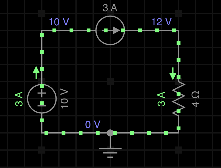
So, we know due to Ohms Law that 3A through a 4 Ohm resistor produces 12V across the resistor. We know the voltage across the voltage source and the current through it as well (3A). Therefore there must be 2V across the current source. I did a simple simulation to show this. Simulation from EveryCircuit

\$\endgroup\$

Your Answer

By clicking “Post Your Answer”, you agree to our terms of service and acknowledge you have read our privacy policy.

Not the answer you're looking for? Browse other questions tagged or ask your own question.