3
\$\begingroup\$

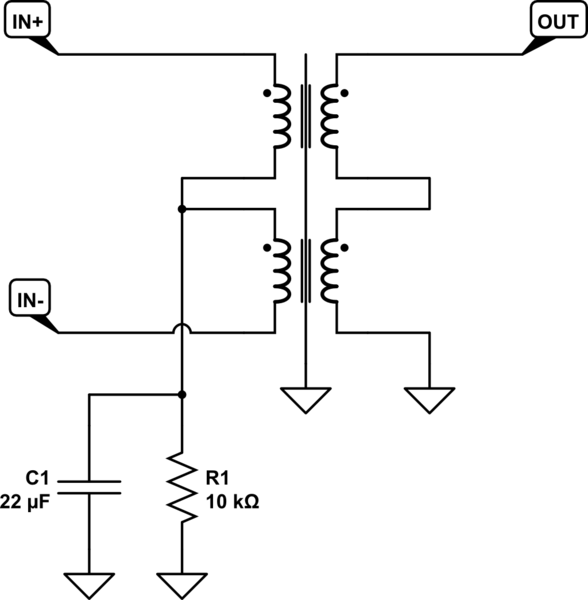
I a audio DAC output stage I have seen the following circuit. It's function is to convert an balanced signal to an unbalanced signal. IN+ and IN- are differential outputs that are biased at 2.5V.

schematic

simulate this circuit – Schematic created using CircuitLab

What is, or could be the purpose of the capactitor C1 in this circuit?

Update:

If my assumptions are correct:

  • R1 sets the center tap to a defined level if IN+ and IN- are idle (at 2.5V).
  • C1 serves as a high-pass filter with a very low threshold frequency.

Does it make sense?

\$\endgroup\$
11
  • 1
    \$\begingroup\$ Your circuit is incorrectly drawn - there is a short across one of the windings. Also, the little detail you supplied does not help. Can you provide a circuit that shows more such as where else the centre pins connect? \$\endgroup\$
    – Andy aka
    Commented Dec 2, 2014 at 10:59
  • 1
    \$\begingroup\$ @Andyaka Thanks for pointing me to the short, I have corrected the drawing. \$\endgroup\$
    – sergej
    Commented Dec 2, 2014 at 12:14
  • \$\begingroup\$ There was more to my comment than just fixing the drawing. \$\endgroup\$
    – Andy aka
    Commented Dec 2, 2014 at 12:15
  • \$\begingroup\$ @Andyaka The function of this circuit is to convert an balanced signalt to an unbalanced signal. Are more details required to explain the purpose of the capacitor? \$\endgroup\$
    – sergej
    Commented Dec 2, 2014 at 12:23
  • 1
    \$\begingroup\$ @Andyaka I came across the schematics at the bottom of this page, but I wasn't sure about the capacitor between the center tap and ground. \$\endgroup\$
    – sergej
    Commented Dec 2, 2014 at 17:45

2 Answers 2

5
\$\begingroup\$

In theory, no connection to the center tap of the primary is actually needed. The "balanced" signal is differential, so only the voltage difference between the two lines matters. The transformer inherently works as a differential front end, since only voltage across its input coil causes and magnetic field that is the coupled to the output coil.

However, you don't want the common mode voltage of the balanced signal to go too far from ground. If totally insulated, it could pick up static electricity and build up to 1000s of volts, eventually arcing over something and causing a crackle sound in the audio. The resistor provides a relatively weak path to ground, but it's plenty low enough to prevent static buildup. The capacitor does the same thing but more so at higher frequencies. At too high common mode frequencies, the inevitable capacitive coupling in the transformer will cause some of the common mode signal on the input to show up as signal on the output. The capacitor provides a more serious connection to ground for AC, while the resistor only a weak connection for DC to avoid ground loops.

Note that since this connection to ground is halfway thru the primary of the transformer, the magnetic field caused by the common mode voltage across one half the winding is offset by the magnetic field caused by the common mode voltage across the other half of the winding.

Personally, 22 µF seems really high to me. I would want to let the common mode float more easily at audio frequencies. I would have been more concerned about squashing the pickup of radio station, while letting pickup from the power line be a common mode signal that the transformer should do a nice job rejecting. The two halves of the primary aren't going to balance exactly, so you don't want to push more common mode signal thru there than you have to.
\$\endgroup\$
2
\$\begingroup\$

This is surely not a protection circuit against input noise in any way. This would be crazy. If it would be meant for the protection of high common mode over voltages AC and DC such voltage should not reach the primary coil of the low voltage transformer at all as it would arc the windings inside the primary coil halves rather than crossing the insulation between primary and secondary coil. Such protection circuit should be applied to In+ and In- in order to keep the suggested kind of high energy noise away from the low signal transformer. And this 22µF capacitor is propably no high voltage bipolar type, is it? In my opinion this has smething to do with the circuit outside the shown detail as suggested by some other contributer here. For me it looks as if this R & C network centers and stabilizes some operational DC between In+ and In- from the circuit left of the shown schematic. Potentially the sourcing amps are powered by a non symmetric PSU where one amp is working in inverted and the other in non inverted mode and their outputs are decoupled from the transformer by line capacitors? In this case the shon R would set the center and the C would stabilize this center in order to not follow the signal.

\$\endgroup\$

Your Answer

By clicking “Post Your Answer”, you agree to our terms of service and acknowledge you have read our privacy policy.

Not the answer you're looking for? Browse other questions tagged or ask your own question.