0
\$\begingroup\$

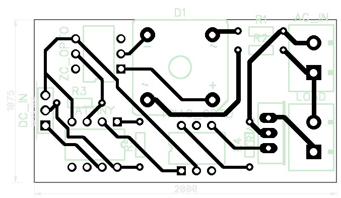
I'm playing around with the idea of adding a capacitive sense switch to an all-metal lamp, and have some questions around safety as I'd, obviously, prefer not to turn the whole thing live.

In the plastic, isolated base, I'll put a 220V->5V SMPS which powers a board with an ATTiny45, opto-isolater/triac, and zero crossing detection circuitry. What sort of trace isolation do I require for the 220VAC? And between the live and isolated side? Anything else that's likely to kill me?

Board top: top
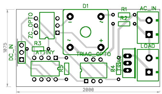
Board bottom: bottom

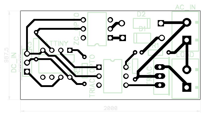
(edit for improvement)

Is the below better? better
\$\endgroup\$
5
  • 3
    \$\begingroup\$ Why do you have such a ridiculous huge bridge rectifier in there just to drive the zero-crossing detector? In fact, if this is just for on-off control, why do you need to detect zero crossings at all? \$\endgroup\$
    – Dave Tweed
    Commented Jan 6, 2015 at 15:45
  • 3
    \$\begingroup\$ Yeah, that trace spacing for a start. You have LV traces about 1mm from mains traces. The closest they should come is the two rows of pins on each opto, about 6-7mm apart. Bottom opto is easy to fix : rotate it 90 degrees. \$\endgroup\$
    – user16324
    Commented Jan 6, 2015 at 15:45
  • \$\begingroup\$ @DaveTweed I was actually going to ask that, but didn't want to conflate questions. I want the ZC for dimming, but can just do half-wave rectification with a single diode I'd think \$\endgroup\$
    – Bryn Divey
    Commented Jan 6, 2015 at 15:52
  • \$\begingroup\$ @BrianDrummond Thanks Brian, exactly the sort of info I was looking for. The opto pin-width sounds like a sensible rule of thumb - I'd used some online calculator but don't think I did it right. \$\endgroup\$
    – Bryn Divey
    Commented Jan 6, 2015 at 15:54
  • 2
    \$\begingroup\$ Re: your edit -- much better! \$\endgroup\$
    – Dave Tweed
    Commented Jan 6, 2015 at 16:44

1 Answer 1

5
\$\begingroup\$

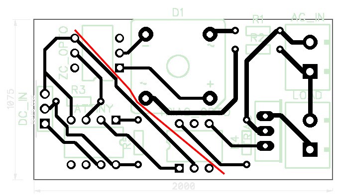
The key concept is that you need to be able to draw a line across your board, with all of the mains-connected traces on one side of it, and all of the isolated traces on the other:

enter image description here

The copper-free gap through which this line runs needs to be at least 6mm wide, in order to provide adequate arc-over and creepage clearance between the two sets of traces.

\$\endgroup\$
1
  • \$\begingroup\$ Thanks Dave - so something like the additional image I've added would be sufficient? \$\endgroup\$
    – Bryn Divey
    Commented Jan 6, 2015 at 16:44

Your Answer

By clicking “Post Your Answer”, you agree to our terms of service and acknowledge you have read our privacy policy.

Not the answer you're looking for? Browse other questions tagged or ask your own question.