0
\$\begingroup\$

For this circuit we're asked to calculate Vo using the 0.7V diode model.
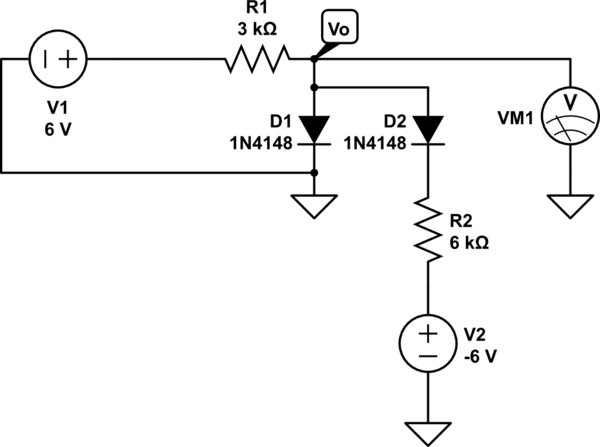
schematic

simulate this circuit – Schematic created using CircuitLab

I understand that when the potential is higher at the anode than the cathode then the diode is in the forward biased direction, current will flow through the diode and a (in this model) a 0.7V drop across the diode will occur.

My guess was that D1 is in reversed bias mode b/c the V2 is at a lower potential than ground, so D1 can be modeled as an open circuit.

I don't know where to go from there, my gut says nodal analysis but I'm not quite sure how to set it up. Plugging this into circuit simulators I get ~525mV when using 1N4004 diodes, but I'm not sure how to calculate this by hand.

\$\endgroup\$
4
  • \$\begingroup\$ Your schematic doesn't have any location labelled as \$V_o\$. \$\endgroup\$
    – The Photon
    Commented Feb 15, 2015 at 0:32
  • \$\begingroup\$ @ThePhoton fixed. \$\endgroup\$
    – MDMoore313
    Commented Feb 15, 2015 at 0:33
  • \$\begingroup\$ when potential is higher at the cathode than the anode then the diode is in the reverse biased direction. \$\endgroup\$
    – nidhin
    Commented Feb 15, 2015 at 6:09
  • \$\begingroup\$ @nidhin thanks, fixed. I knew the polarity but got the terms reversed. \$\endgroup\$
    – MDMoore313
    Commented Feb 15, 2015 at 12:22

5 Answers 5

2
\$\begingroup\$

From the sounds of it, the diode model you are using is the simple "ideal diode" with a fixed forward voltage. This model is an open circuit when \$V_{\textrm{Anode}} - V_{\textrm{Cathode}} < V_D\$ (reverse biased), and a fixed \$V_D\$ voltage supply otherwise (forward biased).

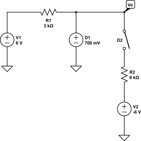
Start by making assumptions about the state of D1 and D2 (for example, D1 is forward biased, and D2 is reverse biased).

Your circuit would then look like this:

schematic

simulate this circuit – Schematic created using CircuitLab

What is \$V_o\$ here? The last step is to check your assumptions on each diode. If the assumptions are correct, the model is applicable. If not, permute your assumptions (ex.: what if D1 is reverse biased, and D2 is forward biased? or D1 and D2 are reverse biased, etc.) Only one of the 4 possible permutations will have a consistent answer.

As a side note, the answer you get will not match what the circuit simulator gives you (though it will be close). This is because the circuit simulator uses a more advanced diode model.

\$\endgroup\$
2
  • \$\begingroup\$ I'm not looking for a handout, or just giving me an answer, but I'm really not sure how to calculate Vo when D1 is open and D2 is shorted, if you could explain that process? \$\endgroup\$
    – MDMoore313
    Commented Feb 15, 2015 at 3:46
  • 1
    \$\begingroup\$ The first step is always to re-draw your circuit with your assumptions (in this case, D2 is a 0.7V supply and D1 is an open circuit). Next, I would use nodal analysis. \$\endgroup\$ Commented Feb 15, 2015 at 4:01
1
\$\begingroup\$

If you run with your guess and either work out the voltage divider or simply apply symmetry (can be done in your head) you get a number for Vo. Since that number is less than 0.7V your guess checks out and D2 is forward biased and D1 is off.

\$\endgroup\$
0
\$\begingroup\$

Start by assuming D1 is open, and D2 is shorted. What is the output? So which way are the diodes biased?

\$\endgroup\$
4
  • \$\begingroup\$ I did assume that, but I don't know how to calculate output. if the -6V were 0V and D2 were shorted it'd be a simple voltage divider, but I'm not sure how to convert that circuit to this one. \$\endgroup\$
    – MDMoore313
    Commented Feb 15, 2015 at 0:19
  • \$\begingroup\$ @BigHomie You don't even have to use a voltage divider to calculate Vo in this case. D1 is reverse biased, so you can remove it from the circuit. If D2 is forward biased, VD2 = 0.7V. So what is Vo? \$\endgroup\$ Commented Feb 15, 2015 at 1:40
  • \$\begingroup\$ @pikafu - He doesn't realize D1 is reverse biased. \$\endgroup\$ Commented Feb 15, 2015 at 1:43
  • \$\begingroup\$ @WhatRoughBeast I thought he was assuming that D1 is reverse biased since he states in his question "My guess was that D1 is in reversed bias mode". \$\endgroup\$ Commented Feb 15, 2015 at 1:48
0
\$\begingroup\$

It looks to me as though, it is a trick question. The V2 supply has the + positive lead hooked to R2. If their is no current flow Vo should be +6 volts. Even if V2 had the negative lead hooked to R2 the diode would be reverse bias and not conduct. Still +6 volts.

\$\endgroup\$
1
  • \$\begingroup\$ That's what I thought at first too! I don't think that's correct though. \$\endgroup\$
    – MDMoore313
    Commented Feb 15, 2015 at 0:50
0
\$\begingroup\$

If you use 0.7V diode model then I think the Vo will be 0.7Volt.

In above circuit D1 is forward biased for v1 but D1 is reversed biased for V2 so I think V2 (-6volt) has no use or contribution because it is blocked by Diode D1, so if used 0.7volt diode model the Vo will be 0.7volt. (In my opinion)

\$\endgroup\$

Your Answer

By clicking “Post Your Answer”, you agree to our terms of service and acknowledge you have read our privacy policy.

Not the answer you're looking for? Browse other questions tagged or ask your own question.