1
\$\begingroup\$

I am trying to control speed of a DC motor using PWM. To reduce coupling of motor noise onto my electronics, I am using a separate power supply for both(LED and Phototransistor) and am planning to interface PWM pin from µC to motor using 6N137 optoisolator. Speed of PWM is about 20KHz as recommended by motor manufacturer.

When I try to test 6N137, when I use a single supply for both input and output, i.e LED and phototransistor everything works according to truth table listed in the data sheet. When I use two different supplies(with or without isolating ground) output is always high irrespective of the input. Can anybody point out my mistake for this behavior? Find attached the schematic and output waveform.
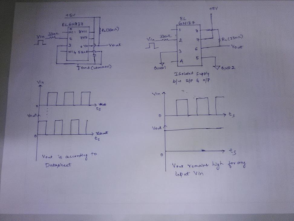
Schematic and O/P

Regards, Ani

\$\endgroup\$
1
  • \$\begingroup\$ In the second circuit diagram, Is pin no 8 connected to 5.0V? Since that is Vcc and must be connected to power supply. \$\endgroup\$
    – AKR
    Commented Mar 20, 2015 at 6:29

2 Answers 2

1
\$\begingroup\$

In the case of the second circuit have you made sure that the GND2 connects to the return of the 5V output supply?

I ask this because if this connection is open it could explain why the coupler is unable to pull the output low. This particular case would be where the GND connection of your scope or meter is properly connected to the GND of the 5V power supply.

\$\endgroup\$
1
  • \$\begingroup\$ Correct. Your above point proved right and it was the GND2 that was left unconnected in the connector. But scope/meter was referenced with GND2. \$\endgroup\$
    – dev.
    Commented Mar 24, 2015 at 3:08
0
\$\begingroup\$

For the second circuit have you made sure that the GND1 connection from pin 3 of the coupler is connected to the GND of the driving circuit?

I ask this because one explanation for the non functioning of the circuit is due to your not getting any current flowing through the input diode. (You could verify input diode current by looking to see if there is a drop across the 330 ohm input resistor when the input is high).

\$\endgroup\$
2
  • \$\begingroup\$ Yes I have made sure about this. I see a correct voltage drop across the LED of 1.4V and at the same time see a high at the output. Also while measuring I am making sure I am referencing against appropriate grounds. \$\endgroup\$
    – dev.
    Commented Mar 20, 2015 at 11:13
  • \$\begingroup\$ By "at the same time" do you mean measuring one then the other? Note what @Michael said about measuring instruments supplying ground paths. \$\endgroup\$ Commented Mar 20, 2015 at 15:05

Your Answer

By clicking “Post Your Answer”, you agree to our terms of service and acknowledge you have read our privacy policy.

Not the answer you're looking for? Browse other questions tagged or ask your own question.