3
\$\begingroup\$

Are you an EE? Do you use TI Op-Amps? then you should know the answer of this question. probably that could be interesting for us.

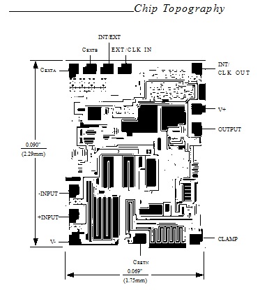
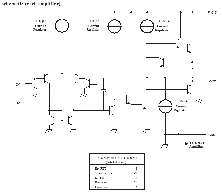
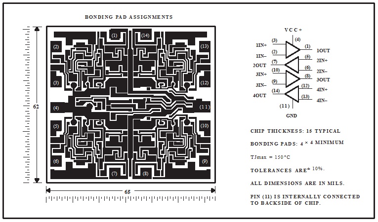
If you take a look at the datasheet of TI(or a few other companies) Op-Amps you will come across with "chip topography" or "diagram(schematic)". for example:

figure1 Source

or:

figure2

Source

or for schematic:

figure3

Questions about the chip topography:

  1. What is/are the usage of chip topography for an EE? because the many of information for the chip topography of a chip is mechanical while we are EE. that's interesting to me that you can see the chip topography of ICL7650 in the MAXIM datasheet but there is no schematic for it. I think the schematic is much more clear than the chip topography then why there is no schematic for it?
  2. Have you had any experience to use chip topography in your design? what was that?
  3. Why while there is a clear schematic, they put chip topography?

Questions about the schematic:

  1. Personally I think there are everything that we need to use for designing our circuit then what's the usage of the schematic? (you can see everything that you need in)

Please tell me all things that we can catch from these stuff.

Thanks in advance

\$\endgroup\$

2 Answers 2

3
\$\begingroup\$

As mentioned in another answer, the die diagram is helpful if you are buying the chip as a bare die and doing chip-on-board or hybrid assembly.

The schematic is also helpful for understanding how to drive the inputs and how to load the outputs. It helps you know tings like whether pull-ups or pull-downs are needed, whether ac-coupling is needed. It might give an idea whether the output is able to source or sink larger currents. In your op-amp example, there's also some indication of how the compensation is done, which will give an idea of what the chip's open-loop frequency response looks like (not just the bandwidth, but also how many poles and zeros).

The component count, which you didn't ask about but is shown in your schematic example, is used in some reliability models. It is combined with the device count of other ICs in the system to estimate the MTBF for the system.

\$\endgroup\$
2
\$\begingroup\$

Chip topography is useful only if you can get the chip as a bare die. You need to know the precise locations of the bond pads in order to wirebond it to the board. Schematics are not exceptionally common, generally you will get block diagrams and simplified schematics of particular components, especially I/O circuitry. Schematics can be useful to understand how the chip works and possibly for building simulation models.

\$\endgroup\$
0

Your Answer

By clicking “Post Your Answer”, you agree to our terms of service and acknowledge you have read our privacy policy.

Not the answer you're looking for? Browse other questions tagged or ask your own question.