Why does the output impedance(Ro) of a common emitter amplifier is considered in parallel with the collector resistance(Rc)...as according to the KVL--->Vcc=IcRc+Vce+IeRe they seems to be in series....??
-
\$\begingroup\$ A schematic would probably make it more clear what you mean by "Ro" and "Rc". \$\endgroup\$– The PhotonCommented May 20, 2015 at 3:15
-
\$\begingroup\$ That said, I am guessing the answer is for the same reason that the equivalent output impedance of a resistor divider is the resistance of the parallel combination of the two resistors. \$\endgroup\$– The PhotonCommented May 20, 2015 at 3:16
-
\$\begingroup\$ I dont have a specific schematic for it..rather you can consider Ro as output impedance of the transistor which is often assumed to be an internal impedance between collector and emitter terminal and Rc is the collecter resistance of an amplifier... \$\endgroup\$– partykidCommented May 20, 2015 at 3:42
3 Answers
If you have two resitors which have one common node, it is IMPOSSIBLE to decide if the are connected in series or in parallel because this only depends on the node where the voltage or current source is connected.
They have to be considered as parallel if the source is connected BETWEEN both resistors (common node, as in your case). If the source drives an open end of one of the resistors they are in series (one common current goes through both resistors subsequently).
-
\$\begingroup\$ ok talking about output resistance ..why it is always adviced to have high output resistance in a current mirror..how exactly it helps@ LvW \$\endgroup\$– partykidCommented May 20, 2015 at 14:22
-
\$\begingroup\$ A current mirror is a controlled current source. And a current source - by definition - must have a large output resistance. In this case, this resistance dominates over all possible connected loads - and determines the current, independent on the load. \$\endgroup\$– LvWCommented May 20, 2015 at 18:31
-
\$\begingroup\$ It means that the current should not change whatever the load voltage be...with small value resistance current changes more on changing voltage across them..and with high value of resistance current change less...but i didn't get your phrase..."resistance dominates.....connected loads"...please simplify.. \$\endgroup\$– partykidCommented May 20, 2015 at 20:05
-
\$\begingroup\$ If you have a series connection of two resistors Ro and RL - and if Ro is much larger than RL - the resulting current is mostly determined by Ro. Hence, Ro dominates as far as the current is concerned. \$\endgroup\$– LvWCommented May 21, 2015 at 7:13
-
\$\begingroup\$ Or can we say it like this..if we change Ro to x ohms the resulting current would change more...in comparison to RL.... if we also change RL to same x ohms the resulting current would change less....Hence Ro dominates RL \$\endgroup\$– partykidCommented May 21, 2015 at 7:58
When we talk about the small signal equivalent output impedance, we are talking about the differential impedance. How much does the voltage have to change to produce a certain change in the output current.
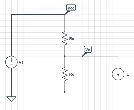
Any resistor divider will have essentially the behavior you describe:

The equivalent output resistance of the divider is \$\dfrac{\mathrm{d}V_o}{\mathrm{d}I_L}\$. The KCL equation for the node Vo is $$\frac{V_o-V_{cc}}{R_c} + \frac{V_o}{R_o} + I_L = 0$$ Rearranging terms $$V_o = \left(\frac{1}{R_c}+\frac{1}{R_o}\right)^{-1}\left(\frac{V_{cc}}{R_c}-I_L\right)$$
The term with \$V_{cc}\$ doesn't affect the derivative so we have $$R_{eq} = \dfrac{\mathrm{d}V_o}{\mathrm{d}I_L} = \left(\frac{1}{R_c}+\frac{1}{R_o}\right)^{-1}I_L$$
where I've fudged the sign, because I should have drawn the \$I_L\$ source facing the other way to begin with.
And that's just the formula for resistors in parallel so $$R_{eq} = R_c || R_o$$
Another way we remember this is that the voltage source (V1) has an equivalent resistance of 0 in the small-signal circuit, and after replacing V1 with a short circuit to form the small signal circuit we immediately see that \$R_c\$ and \$R_o\$ are in parallel.
The small-signal equivalent circuit for a common emitter amplifier has an output circuit (between collector and emitter) that comprises a current generator in parallel with the output resistance, Ro. The load resistor, Rc, is also connected between collector and emitter because the collector power supply looks like a short-circuit to a.c. signals (it's internal resistance is all that an a.c. signal sees, and this is small compared to Rc). Hence the top end of Rc is seen as being connected to the emitter or ground. So Rc is effectively in parallel with Ro for small signals.
