In your question, you said "each subscriber gets their own line for the last mile." For a long time, all subscriber's lines went all the way to the central office (CO). 1000 subscribers meant 1000 telephone pairs. If a telephone line goes longer than 18,000 feet, degradation occurs due to shunt capacitance. So loading coils were used to counteract this. Unfortunately, loading coils don't work with DSL. So this became an issue.
Multiplexing of subscriber lines (many down to one and vice versa) was invented to handle the situation where there aren't enough wires to handle each subscriber (for example, a new neighborhood builds up practically overnight, and it was too expensive, or would take too long, to lay a new thousand pair cable). It also allowed long virtual circuits without the use of loading coils. The "last mile" refers to the length of physical subscriber line (copper pair) from the subscriber's premises to the multiplexing equipment. "Last mile" may be just a few yards if the multiplexing equipment sits next to your house.
As far as I know, Frequency Division Multiplexing (FDM) has never been used for subscriber line multiplexing, probably because of the size of the equipment needed and its rather fragile nature -- the equipment has to work outside in environments from -20 °F in Minnesota to 115 °F in Arizona for example.
Instead, this is all done digitally using Time Division Multiplexing (TDM). The particular application is called Digital Loop Carrier (DLC).
In one of the original systems, analog phone calls were digitized at 8000 samples per second (to provide adequate quality of the 3400 Hz voice band per Shannon's sampling theorem). Each conversation would be allocated one of 24 time slots. These samples would then be combined as follows:
$$(8 \frac{bits}{channel}\space x\space 24 \frac{channels}{frame} + 1 \frac{framing bit}{frame})\space x\space 8000 \frac{frames}{second} =$$
$$1544000\frac{bits}{second} = 1.544\frac{Mbit}{second}$$
This is called a T1 line. So you would get a concentration of 24 to 1.
At the other end, the samples would be converted back to analog (for a old-fashioned analog-type telephone office, like crossbar) or left in digital form (for a newer digital office like ESS).
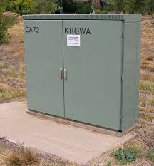
So there were no carriers frequencies, modulators, or amplifiers, just a few filters -- mostly low pass to filter out any high frequency noise on the lines. As a result, the equipment was not as fragile as that used for FDM and could be placed inside a cabinet along the sidewalk somewhere in the neighborhood:

Nowadays, this type of equipment may be used to connect to many more subscriber lines, by concentrating the lines onto a fiber optic cable which is run to the central office. It is usually combined with the equipment needed to provide DSL access plus television in some instances to the subscribers. The combination of the fiber optic interfacing with the physical subscriber lines is sometimes called "fiber to the curb".
As Jan Böcker points out in his answer, it is possible wavelength division multiplexing could be used with the optical fiber, if more than one optical signal is used. But I very much doubt that would be needed in this application. And anyway, it is not the same as using FDM on an individual subscriber line.
So, I don't think you're going to find an example where each telephone subscriber is frequency multiplexed onto a single wire and has its own filter.

