26
\$\begingroup\$

I've been playing with a 5m long RGB LED strip, with 300x surface mount 5050 RGB LEDs, but can't understand why the strip isn't as bright or drawing as much power as I was expecting.

I've had a look at Arduino and 5A 12Volt driver, which appears to be talking about the same sort of product, but the answers there don't help me understand.

From the spec:

LED Light Source  5050 SMD LED
LED Beam Angle    120 Degree
LED Power         14.4W/Meter, 0.24W each LED
LED Quantity      60pcs LEDs/Meter
Working Voltage   DC 12V
Common Type       Anode

The reel however says something a little different:

Model:            5050-1M-60LED
Color:            W/RGB
Voltage:          DC-12V
Power:            72W/5M/5A

The IR controller is connected up via a 4 way ribbon cable, one wire for each colour and one for the 12v line. Each 5cm section contains three 6 pin RGB surface mount LEDs and three 1206 SMT (resistors?) labelled 151 (for Green & Blue I think) and one labelled 331.

The IR controller manual & case detail the following spec:

Output:           Three CMOS drain-open output
Connection mode:  common anode
Output current:   < 6A (on case)
                  < 2A each color (in manual)

So, I was expecting when I powered it up and set it to full brightness Red, Green or blue, for 2A to be drawn, and when I switch it to white, for 6A to be drawn.

That's not what I'm seeing though. At 11.95v I'm seeing each colour on it's own draw between 1 and 1.3A, while full brightness white only draws 2.2A, or substantially less than the three combined!

On a hunch, I cranked up the supply voltage to 14.4V (given the 72W/5A on the reel) and now I get much closer to what I expect, but the full brightness white is still drawing well below the 72W I was expecting. The full results were:

Red   (full brightness)    1.325A  11.95V  15W    2.000A  14.4V  29W
Green (full brightness)    1.021A  11.95V  12W    2.000A  14.4V  29W
Blue  (full brightness)    0.996A  11.95V  12W    1.978A  14.4V  28W
White (full brightness)    2.218A  11.95V  27W    3.961A  14.4V  57W

Is there something I'm misunderstanding about how these circuits should behave?

Is it likely to just be the IR controller limiting the current available to the LEDs, thus resulting in them being less bright and drawing less current?

Could I just hook the 12v supply directly to the LED strip without the LED controller to measure current and get a feel for brightness, or am I likely to burn out the LED strip without the 'proper' controller?

I haven't yet cracked open the IR control box, to look at what components it contains, but would be happy to do so if requested...

... Opening up the IR controller, the PCB is marked EC-LED-19A, so it is probably this product but that still doesn't give me a datasheet. The significant components seem to be an unlabelled 14pin IC (presumably a PIC), an FT24C02A serial eeprom, a 78L05 regulator and 3 more SMT caps and 68ohm SMT resistors. Each of the RGB channels have a 10k resistor, a 2k resistor and a 3 pin SMT package labelled WFAON, which I can't find a datasheet for.

It is possible that LED strips: 46% resistive losses? may be able to help answer this question more comprehensively.

\$\endgroup\$
4
  • 1
    \$\begingroup\$ The specifications your quoting are most likely maximum ratings, not nominal operating values. \$\endgroup\$
    – Mark
    Commented Sep 13, 2011 at 3:09
  • 1
    \$\begingroup\$ Can you give us the full specs/datasheet of the IR controller? It is likely a constant current driver, and will probably be limiting current according to some control signal. Changing supply voltage is "inadvisable" before you're sure what is going on. \$\endgroup\$
    – Oli Glaser
    Commented Sep 13, 2011 at 8:03
  • \$\begingroup\$ No, the recent question on 46% resistive loses doesn't address your issue. There the question is on effeciency, the power is still drawn.but wasted in resistive heat. Here, your issue is most likly due to the controller and undersized power supply. A direct connection to a 6Amp 14V power supply at both ends of the reel should produce close to 5.8Amps. \$\endgroup\$
    – Passerby
    Commented Oct 30, 2014 at 13:50
  • \$\begingroup\$ @Passerby - I updated my question, as much as anything, to remind myself to measure the Vf's and model the circuit, to see how much of an effect the resistive losses will be having, hence the "help answer". \$\endgroup\$
    – Mark Booth
    Commented Oct 30, 2014 at 15:54

6 Answers 6

20
\$\begingroup\$

I once had the same problem and could not figure it out until I measured the voltage on the other end of the strip: It was dropping whole 3V accross the entire length! You could even see the difference in brightness when comparing the first and last LED.

Consider the resistance of the 5 meter trace of copper. These strips are usually produced on cheap flexible PCB with the default (35um) copper layers and have very high resistance.

It is clear that these LED strips will, at least in one piece, never meet the spec printed on them.

\$\endgroup\$
2
  • \$\begingroup\$ Excellent point - that makes sense, you would need some pretty thick traces at that length and current not to drop significant voltage. Running a quick calculation, a 5m long, 35um thick, 5mm wide trace has ~0.5 ohms resistance, so at the 6A full rating would drop 3V. 5mm is pretty wide for your average trace, so I imagine it could be even worse on these boards if they did not consider this at all. \$\endgroup\$
    – Oli Glaser
    Commented Sep 14, 2011 at 14:54
  • 1
    \$\begingroup\$ Indeed, I recently bought a "15 meter led strip" which is in fact 3 strips that you connect together. After 3 meter I get a noticable drop in luminosity, after 10 meter it's half the luminosity of the first led. Do they actually sell 15M led strip with large enought trace out there? \$\endgroup\$ Commented Mar 31, 2014 at 11:28
11
\$\begingroup\$

Regardless of whether the LED controller is PWM or 'Analogue', some LED strips do indeed drop 2-3V at the end of a 5m roll.

Solution: Feed all 4 wires from the LED controller to both ends of the strip - not just one end. This is called dual-feeding. For a half-way approach, just dual feed the 12V line (common anode) or GND line (common cathode) since this line is delivering the sum of the RG&B currents and hence dropping 3 times that of the RG&B lines.

\$\endgroup\$
3
  • 2
    \$\begingroup\$ I've tried dual feeding, and managed to get the current draw up to about 2.5A without over-volting, but it's still nowhere near the full 6A it should be able to draw. I think I have a cunning solution though, which I will post here when I've had the time to do a few more tests. \$\endgroup\$
    – Mark Booth
    Commented Oct 17, 2011 at 12:43
  • 1
    \$\begingroup\$ Please post your cunning solution, even if it doesn't work. It's good to see what approaches people take. \$\endgroup\$
    – par
    Commented Oct 31, 2014 at 23:37
  • \$\begingroup\$ Another possible option is to 'mid feed' by soldering the 4 supply wires into the middle of the strip somewhere. That way you're feeding 2 x 2.5M, rather than 1 x 5M. \$\endgroup\$ Commented Feb 24, 2017 at 13:57
7
\$\begingroup\$

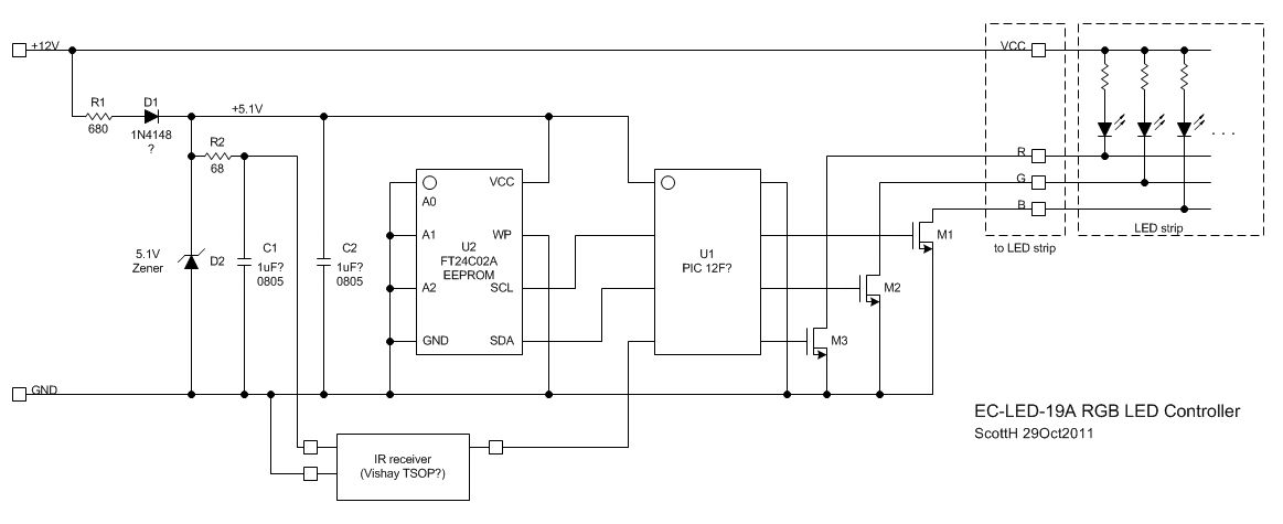
Here is some info on the EC-LED-19A circuit.

The controller is modulating the ground side of the R, G and B lines. The diodes are connected common anode to supply, and the grounds are switched through the (presumably) MOS switches (WFA0N). You are corrected about the EEPROM, and the uC pinout matches a PIC 12F275 or similar. I'm not sure why they used the external EEPROM when the PIC uC's allow you to write data back into the internal EEPROM in the part... perhaps it's a cheaper write-once (PROM) uC? The board appears to use a simple 5.1V Zener diode for a cheap regulator. This one has empty footprints for a 7805 or similar voltage regulator, but for this application a simple resistor (680 ohm) and Zener are fine. There's a reverse protection diode, as well.

[edit - I've added a schematic diagram, below.]

For most colors, two of the lines are either constantly on or off and the third is pulse-width modulated at a 500Hz rate. (measured with an o-scope)

There's a similar circuit on Instructables here: http://www.instructables.com/id/How-to-fit-LED-kitchen-lights-with-fade-effect/step2/Fader/

I ordered mine off eBay... and I was hoping to have a continuously adjustable level of each color, so I'll probably put together my own board for this... though I could just replace the uC with one with a similar pinout and leave a two-wire programming connector in there.

As to the power draw, for the "white" setting, it looks like two of the strings (blue and green, I think) are at full power while the other (red) is pulse width modulated with less than 50% duty cycle (more like 30%). So that might explain why at full brightness on the white setting you'd seeing about 75% of full current. As to the larger difference from 6A down to 2A, the strip is spec'd at 14.4W/m at 12V, or 1.2A/m or 6A total for your 5m strip. I'd suspect the drop in voltage down the strip may have a lot to do with this, as others have suggested, combined with the PWM cycling on one string.

-Scott enter image description here

\$\endgroup\$
4
\$\begingroup\$

Thanks for the added info.
It seems this may not be a constant current controller. Reasoning based on:

  1. It is not listed under the "Constant current Controllers" heading on their website, just under "IR controllers"
  2. It shows the LEDs connected with a resistor, probably to limit current (not a sense resistor as no wire from top of resistor fed into controller. You mention what are almost certainly resistors of probably 150 and 330 ohms which will limit the current, these would not be present in a constant current controller (usually a <10 ohm sense resistor instead)

I think it may be controlled by PWM of the open drain. One way to confirm would be to hook it up to a scope and look at the waveform at the top of the resistor whilst changing brightness levels. If no scope a multimeter on AC might provide some clues also, but some multimeters don't work so well for this kind of thing.
In any case if it is not constant current, then changing the voltage will work to provide more current at max setting (and your test results are another clue that it is not), just be careful not to exceed the power ratings of either strip or controller, and keep the voltage within, say 2V above nominal rating and I think all should be fine.

\$\endgroup\$
2
  • \$\begingroup\$ Thanks Oli, I was assuming this was a PWM controller. I don't have a scope but my Fluke 79III reads between 125Hz and 440Hz when going from min to max brightness. \$\endgroup\$
    – Mark Booth
    Commented Sep 13, 2011 at 23:07
  • \$\begingroup\$ @Mark - Yes, initially I hadn't looked closely enough and missed the resistor part so assumed constant current. According to what the Fluke says, it might be Pulse density modulation then. Either way, raising the voltage a bit should be okay, I would probably keep it to around 14V though, as the internal circuitry might not be happy with much more (unless you maybe supply the LEDs with a separate higher source and tie grounds together, though I'd still be careful). \$\endgroup\$
    – Oli Glaser
    Commented Sep 13, 2011 at 23:38
4
\$\begingroup\$

Great posts. I have exactly the same LED strip, with presumably the same controller, as it came out in a kit. What I have noticed is that at White with full brightness, one portion (the end of the strip) gives out a hint of pink, instead of full white, while the beginning of the strip (near the plug) gives out proper white. I guess this is because of the drop in voltage. I'll try to solve this by feeding both ends with power.

As far as amperage is concerned, it is obvious that the controller is limiting the amount of current so as to make white appear approximately as bright (no more, no less) than other colors, because if it went for full 6A on the white, it would appear 3 (or near three) times brighter than say pure red, pure blue, and that would presumably be a strain on the eyes. This considering that no other colour, i.e. diode combination can reach anywhere near 6 A. The controller is obviously equalizing the current so that no color appears much brighter than the next. Also, from the point of view of consumption, I am actually glad that your readings confirm what I've inferred that in no way does the strip consume full 72 watts of power at max, I find that conforting in the expectation of my next power bill. :)

But I guess increasing the voltage to 14 gives an overall brigher output, which is something I may try on my power supply. Thanks for the info.

\$\endgroup\$
2
  • \$\begingroup\$ I think you may be overestimating how complex/clever the controller is, given ScottH's answer. I'm now pretty certain, given Manuel J.'s answer that the resistance of the flexible PCB is the determining factor in this system. I have more experiments to try, so I'll report back here when I have more information. \$\endgroup\$
    – Mark Booth
    Commented Feb 8, 2012 at 15:47
  • \$\begingroup\$ The cheapness of the controller may also be the limiting factor. It's output stages may simply not be able to supply the full power. The way to find out is to ask for full red, measure the current. Then green, then blue. I'll bet they add up to more than the total when you ask for full white. \$\endgroup\$ Commented Feb 24, 2017 at 14:03
2
\$\begingroup\$

I think I have an answer for your problem. I was doing my first resistor calculation for 3 LEDs. I decided to confirm the calculation by checking against the resistors they use in the LED strips (151ohm in a 5050 strip). Odd, I got a way different result.

For 5050 Vf=3.0 to 3.4V, 3.2V typical, therefore 12-3x3.2=2.4V for the resistor At current of 60mA that's 40ohm min

I'm guessing the reason is that they are designed for a worst case scenario which would be in cars. While car batteries are only 12V, the alternator exceeds 14V. Eg at 14.5V 85ohm min.

\$\endgroup\$
1
  • 3
    \$\begingroup\$ This is old, but LEDs in series do not consume 3 times the current, they use the same current. So a 3 led section in series with 20ma typical per led, would only consume 20ma. So 2.4 V / 0.020 A = 120 ohm. Next common 10% resistor value is 150. So 16ma actual. Per color. Resistor varies for Red obviously. \$\endgroup\$
    – Passerby
    Commented Feb 22, 2013 at 7:45

Not the answer you're looking for? Browse other questions tagged or ask your own question.