0
\$\begingroup\$

This extends my previous question involving same circuit, information replicated here for convenience and independence of this question.

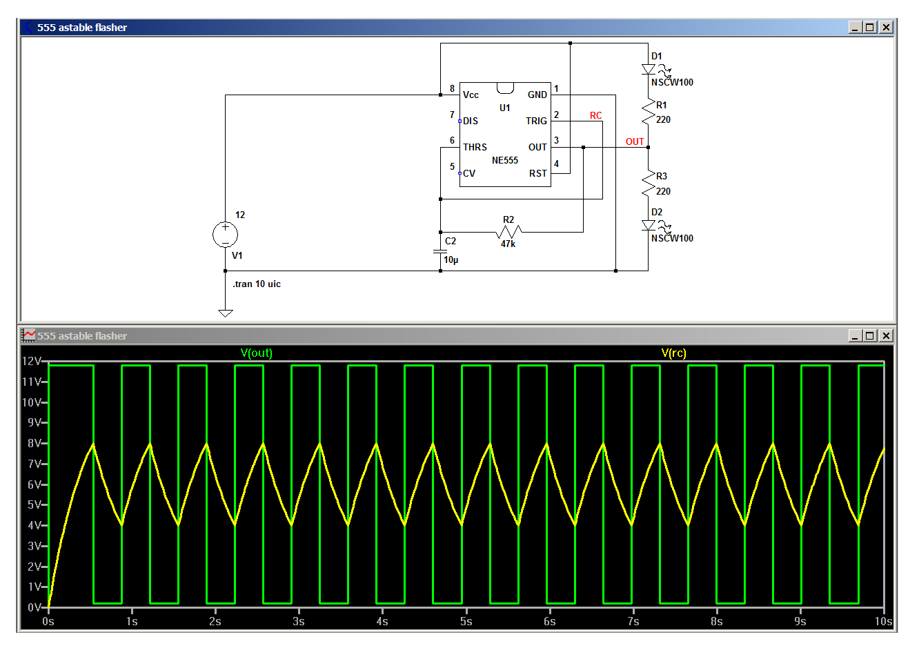
The following circuit schematic:

enter image description here

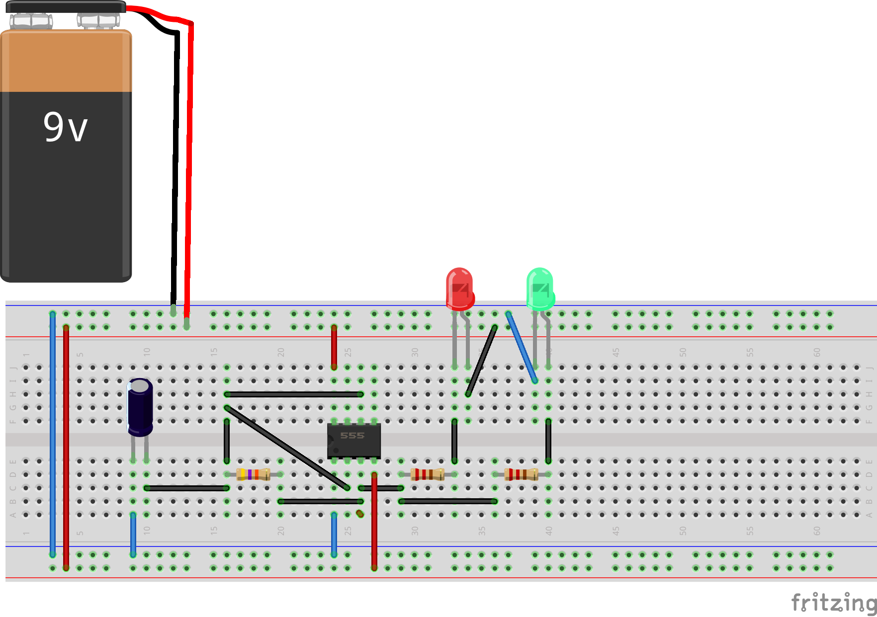
Has been connected as shown here:

enter image description here

However, on connecting it to the power source (now a 12VDC lead-acid battery, with unloaded terminal voltage as bit over 13VDC, from a robotics kit), I see that only the green LED is glowing (permanently lit), and red LED is unlit. The expected behaviour is both flashing alternately (aka Railroad crossing lights). What all could be wrong here ?

\$\endgroup\$
10
  • \$\begingroup\$ Both your LEDs in the schematic are marked 'red', rather than one red and one green; Also, which specific version of the 555 are you using? \$\endgroup\$ Commented Dec 14, 2015 at 10:35
  • \$\begingroup\$ Oops, while schematic does indeed say red LED for both, I've just used a combination of red and green in the breadboard layout diagram. As per the schematic, the lower LED glows steady, while upper LED remains unlit. It is NE555 (not the low-voltage type). \$\endgroup\$
    – bdutta74
    Commented Dec 14, 2015 at 10:44
  • \$\begingroup\$ Your schematic is a bit unusual as it does not use the discharge pin (pin 7). I'm unsure how the 555 likes this, I never tried this. Theoretically it should work though. The green led is the one to ground right ? Then the output is high and the 47k resistor must charge the 10uF cap. Get your multimeter and measure this ! NB, also place a 10 uF decoupling cap across the supply rails just to be sure (it is good practice to have this). \$\endgroup\$ Commented Dec 14, 2015 at 11:13
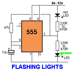
  • \$\begingroup\$ Like this schematic ? \$\endgroup\$
    – bdutta74
    Commented Dec 14, 2015 at 11:22
  • \$\begingroup\$ Yes exactly, that looks more like the standard way to use a 555. \$\endgroup\$ Commented Dec 14, 2015 at 12:27

2 Answers 2

1
\$\begingroup\$

The circuit itself is fine as long as there's enough headroom for the output to swing between 1/3 and 2/3 Vcc, and that's not a problem with a 12 volt supply and little LED loads.

According to LTspice, the circuit should work, so the only things I can think of are that maybe your wiring is different from what you've shown or you've got a bad 555.

enter image description here

\$\endgroup\$
0
\$\begingroup\$

If your circuit is actually built on the breadboard as shown, you have a breadboard problem.

The long supply rails (two along the top, two along the bottom) are physically split in the middle.

Either place jumpers across the breaks in those rails or move all of the circuit to one side of the breadboard.

\$\endgroup\$

Your Answer

By clicking “Post Your Answer”, you agree to our terms of service and acknowledge you have read our privacy policy.

Not the answer you're looking for? Browse other questions tagged or ask your own question.